6. FISH POND CONSTRUCTION
6.0 Introduction
1. When the construction site has been prepared, the fish pond and its water control structures can be built. This chapter shows you how to construct the fish pond, while the next chapters of this manual, deal with water control structures.
2. Dikes are the most important part of a fish pond, as they keep the necessary volume of water impounded and form the actual pond; their design and construction is particularly important. You will learn more about pond dikes and earthwork calculations in the next three sections, before learning how to stake out and construct the four main types of pond.
3. You will find it useful to have a notebook in which to make any calculations required and, if available, some squared or graph paper for sketching out and measuring pond and dike shapes.
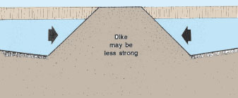
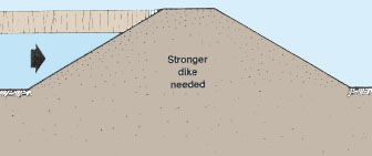
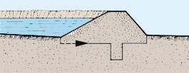
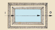
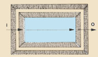
Note: an intermediate dike separating two ponds may not need to be as strong as a perimeter dike, so long as the water pressure is more or less the same on both sides. If one pond needs to be drained while the adjacent one remains filled however, water pressures will be similar to those in perimeter dikes, and the dike should be stronger.
 |
Equal water pressure
 |
|
|
Unequal water pressure
 |
Ensuring impermeability
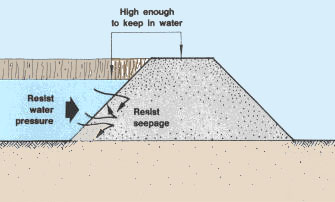
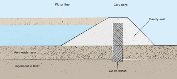
3. Impermeability of the dike can be ensured by:
- using good soil that contains enough clay (see Soil, 6);
- building a central clayey core when using pervious soil material;
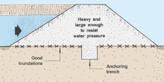
- building a cut-off trench when the foundation is permeable;
- applying good construction practices (see Section 6.2);
- ensuring that the thickness of your dike is appropriate.
|
Diagram of a pond dike built using sandy
soil with a clay core and cut-off trench to ensure impermeability |
|
Good dike |
Bad dike |
|
|
The better the soil the thinner the dike A Wet zone of dike in clayey soil |
Clay core lowers saturation line
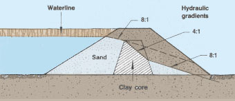 |
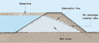


Note: a dike entirely built of good soil is said to be impervious when the upper limit of its wetted zone, the saturation line*, progresses through the dike so as to remain inside. The better the soil for dike construction, the more the saturation line is deflected downward, and the thinner the dike can be. The slope of this saturation line, the hydraulic gradient*, usually varies from 4:1 (clayey soil) to 8:1 (sandy soil). As shown, a clay core will affect this hydraulic gradient.
Choosing the right height
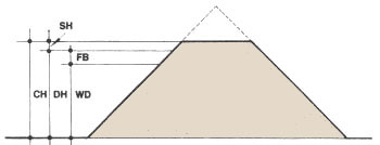
4. To calculate the height of the dike to be built, take into account:
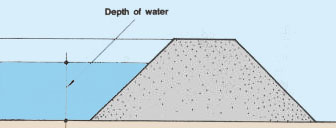
- the depth of the water you want in the pond;
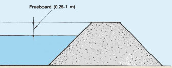
- the freeboard*, which is the upper part of a dike and should never be under water. It varies from 0.25 rn for very small diversion ponds to 1 m for barrage ponds without a diversion canal;
- the dike height that will be lost during settlement*, taking into account the compression of the subsoil by the dike weight and the settling of fresh soil material. This is the settlement allowance which usually varies from 5 to 20 percent of the construction height of the dike (see Section 6.2 and Table 28).
|
Factors to be considered in calculating dike heights |
||
 |
 |
|
 |
||
5. Accordingly, two types of dike height may be defined:
- the design height DH, which is the height the dike should have after settling down to safely provide the necessary water depth in the pond. It is obtained by adding the water depth and the freeboard;
- the construction height CH, which is the height the dike should have when newly built and before any settlement takes place. It is equal to the design height plus the settlement height.
6. You can determine the construction height (CH in m) simply from the design height (DH in m) and the settlement allowance (SA in percent) as follows:
|
CH = DH � [(100 - SA) � 100] |
|
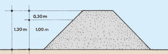
Example If the maximum water depth in a diversion pond of medium size is 1 m and the freeboard* 0.3 m, the design height of the dike will be DH = 1 m + 0.30 m = 1.30 m. If the settlement allowance is estimated to be 15 percent, the required construction height will be CH = 1.30 m � [(100 - 15) � 100] = 1.30 m � 0.85 = 1.53 m. |
Design height and construction height
WD =Water depth |
|
|
Calculating construction height (diversion
pond) 1.30 m � [(100 - 15) � 100] = 1.30 m � 0.85 = 1.53 m |
||
|
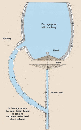
7. In barrage ponds with a spillway, the design height of the dike is calculated slightly differently (see Sections 11.3 and 11.4, Pond construction, 20/2), the freeboard being added above the maximum level of the water in the discharging spillway. Note: the water surface in your pond will be horizontal and therefore the top of your dike should also be horizontal, from the deepest point of the pond to its shallowest point. Determining dike thickness8. A dike rests on its base. It should taper upward to the dike top, also called the crest or crown. The thickness of the dike thus depends on:
9. This, together with the height of the dike, will determine the width of the dike base (see Table 27 for examples).
10. Determine the width of the crest according to
the water depth and the role the dike will play for transit
and/or transport. |
 |

(c) It should be safe for the transport you plan
to use over it:
Note: these dimensions may be slightly reduced for very small rural ponds. |
Factors to be considered in determining
|
|
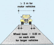 |
Crest width at least equals water depth
 |
|
TABLE 27
|
||||||||||||||||||||||||||||||||||||||||||||||||||||||||||||||||||||||||||||||||||||||
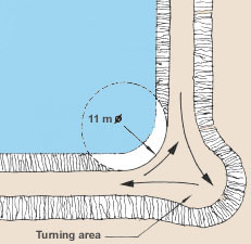
11. Not all the dikes of your fish farm are to be used by vehicles (see Section 1.8). But additional dike width may be required at turning points, based on the diameter of the turning circle of the vehicle used:
|
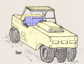
Light pickup truck
 |
|
|
Diameters of turning circles needed for
the use of various vehicles on the top of dikes
|
||
|
Standard tractor
 |
Two-wheel tractor
 |
|
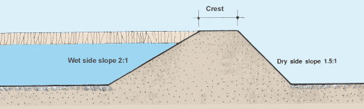
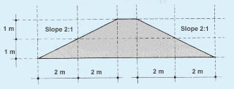
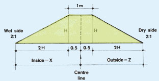
12. In individual ponds, dikes have two faces, the wet side inside the pond and the dry side or external side. These two sides should taper from the base to the top at an angle that is usually expressed as a ratio defining the change in horizontal distance (z in m) per metre of vertical distance as, for example, 2:1 or 1.5:1.
 |
|
Example In a dike with side slope 2:1, for each 1 m of height, the base width increases on each side by 2 x 1 m = 2 m. |
Note: to express the side slope of dikes in other ways, you can use the chart provided here:
|
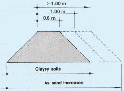
13. The side slopes of each dike should be determined bearing in mind that:
- the steeper the slope, the more easily it can be damaged;
- as the soil becomes more sandy, its strength decreases, and slopes should be more gentle;
- as the size of the pond increases, the size of the waves increases and erosion becomes stronger;
- as the slope ratio increases, the volume of earthwork increases, and the overall land area required for the ponds increases;
- a higher slope ratio makes it easier when using a bulldozer to build the dikes.
14.Usually side slopes of dikes vary from 1.5:1 to 3:1 depending on local conditions. The slope of the dry side can be made steeper than the slope of the wet side. (see Table 27 for various sizes of fish ponds and two groups of soil.)
15. In some cases, you may wish to change the slope, for example:
- to provide an easily accessible area for harvesting or operating a monk (see Section 10.7).
- to deepen the pond near the edges to discourage weed growth or bird predation;
- to make edges shallower for good fry feeding.
16. However, you may have to spend more time in maintaining these dikes.
|
Remember: the thickness of intermediate dikes can be reduced when resistance to water pressure and impermeability are less important. |

6.2 Compacting earthen dikes |
||
Expansion, compaction and settlement of soils |
||
| 1. When earth is disturbed, for example when
it is excavated in preparation for using it to construct dikes, it
normally becomes looser, more permeable and less stable. Its volume
expands, which is known as bulking.
2. When disturbed earth is compacted, for example during dike construction, its volume decreases. Later, as the soil settles, the volume is further reduced. 3. Therefore several different but related measurements of earth volumes can be defined:
4. Table 28 shows typical characteristics of different soils concerning:
5. It also shows the effect of various degrees of compaction and rain exposure on further settlement. |
Some different but related measurements of earth volumes Note: as a rough estimate, considering that expansion and compaction/ settlement factors are similar, the undisturbed volume equals the design volume. |

6. The primary objectives of dike compaction are to start the settling of freshly placed earth, to reduce water permeability, and to strengthen the dike to keep any part of it from sliding away.
Determining the potential for compaction
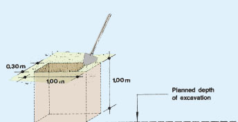
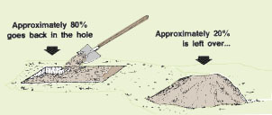
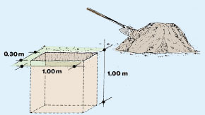
7. You can estimate the bulking of any earth material and determine its potential for compaction by measuring out a known volume of material on the site to be excavated, digging down to the intended excavation depth if possible. You can then either measure the earth volume (for example with buckets, boxes, etc.) or fill the earth back into the test hole and measure the surplus. You should then be able to compact at least 80 percent of this surplus back into the hole by ramming or stamping the soil.
Example
Using a 0.30 x 1 m trench, dig to a 1 m depth. The original earth
volume = 0.30 m3 .
The earth is filled back, leaving a surplus of 0.06 m3 or
60 l.
(a) Estimate bulking
-
expanded volume = 0.30 m3 + 0.06 m3 = 0.36 m3
-
bulking (in percent) is obtained as:
[(expanded volume - undisturbed volume) � undisturbed volume] x 100
= [(0.36 m3 - 0.30 m3) � 0.30 m3] x 100
= (0.06 m3 - 0.30 m3) x 100 = 20 percent.
(b) You should expect to be able to compact at least 80 percent of the surplus (the difference between the expanded volume and the original undisturbed volume): 0.06 m3 x 0.80 = 0.05 m3 . The compaction potential is calculated as: (0.05 m3� expanded volume) x 100 = (0.05 m3� 0.36 m3) x 100 = 13.9 percent of the expanded volume.
|
Dig a test hole
 |
Then, either measure the earth volume ...
 |
|
|
... or put the earth back in the test hole to see how
much it takes... |
||
8. If the site soil was initially loose, you may be able to compact it into a smaller volume than the original one. To define the compaction potential, you can then measure the loose earth required to fill the hole back up to the original level.
Example
A 0.30-m3 trench is dug and the soil is stamped back, requiring 0.06 m3 of loose fill to make it level. The compaction potential of the original soil equals (0.06 m3 � 0.30 m3) x 100 = 20 percent
9. Make note of the basis on which the above calculations are made, that is, whether the compaction potential is related to the expanded soil volume or the original soil volume. Be certain to understand the relationships between undisturbed, expanded, construction and design volumes, as explained earlier.
|
Dig a 0.30 m3 trench
 |
If the earth of this site is loose, you will
need more earth
|


Compacting for best results
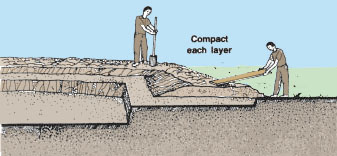
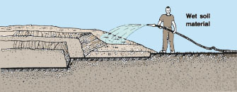
10. To compact successfully, air and water are expelled from the soil so that its mineral particles can settle very tightly together. For best results, you therefore should always:
- place and compact the soil in thin horizontal layers about 15 to 20 cm thick, so air and water can be expelled easily;
- wet the soil material to its optimum moisture content for compaction (see Soil, 6, Section 10.2);
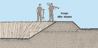
- finish off the slopes of the completed dike to form a well-compacted surface.
| Note: if the soil to be compacted can be formed into a firm ball that sticks together, the moisture content is adequate for immediate compaction. If the soil is too wet, you should let it dry through evaporation for a while. If the soil is too dry, you should water it slightly and mix well to make it homogeneous. |
Good soil material for compacting will stick together
|
|
 |
 |
|
 |


Compacting soil by hand
11. To compact thin layers of soil by hand, you can use simple tools such as:
- a thick stick or the bottom part of a palm frond;
- a thick stick rounded at one end for pounding vertically, for example soil in a trench;
- a hand tamper, a metal or concrete weight (maximum 4 to 6 kg) attached to a wooden handle, with a surface area of about 150 cm2, which you can make or buy cheaply from hardware stores (see also note at the end of the section).
|
12. Hand compacting is generally suitable for small dikes, typically 1 to 1.5 m in height and up to 1 m top width, or smaller if soils are not of good quality. Note: you can easily make a hand tamper using scrap metal fittings, a section of pipe filled with sand and a hardwood handle Various compacting tools |
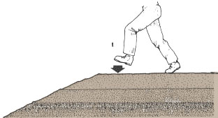
Note: for clays and similar soils, it may be better to use a kneading action, for example by using the heel of the foot. Compacting with the feet |
|
 |

Compacting soil with machinery
13. As the dikes and the area to be compacted increase in size, it is better to compact mechanically.
14. For relatively small compaction jobs, you can use vibration plates and percussion tampers called frogs. For bigger jobs, it is usually sufficient to use construction equipment such as tractors and trucks to compact the earth fill by running over it repeatedly. Special compaction equipment such as sheepsfoot rollers, steel-wheel rollers and pneumatic rollers can also be used, if available, under competent supervision. Average output per working hour (m2/h per 25-cm layers) for various compactors are as follows:
Note: the compaction of non-cohesive soils such as sand requires heavy pressure (weight) and, if possible, vibration. On the other hand, the compaction of cohesive soils such as silt and clay requires a kneading action. Thus to compact a clayey soil you cannot use a normal steelwheel roller which would compact a surface layer only, but you would need a sheepsfoot or pneumatic roller (see Section 10.2 and Table 26, Soil, 6).
|
|
|

|
Compacting small areas
|
||||
|
Vibration plate
 |
Percussion tamper (frog)
 |
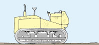
Tracked vehicle
 |
||
|
Compacting larger areas
|
||||
|
Sheepsfoot roller
 |
Vibration roller
 |
Pneumatic roller
 |
||
|
Steel-wheel roller
 |
||||
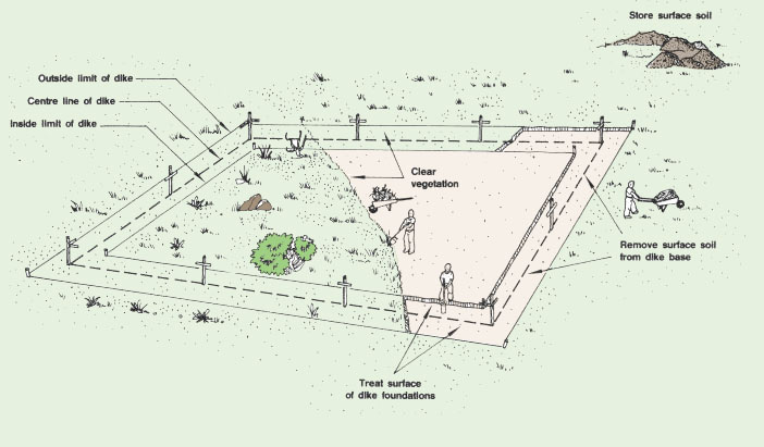
6.3 Preparing the foundations of the dike
1. After clearing the site, removing the surface soil and marking out the position of the dike, the foundations of the dike should be prepared. This may include:
- treating the surface of the foundations;
- excavating and backfilling the cut-off trench;
- excavating and backfilling an existing stream channel.
Treating the surface of the foundations
2. The surface of the dike's foundations needs to be well compacted, so that the dike can be solidly attached without any risk of it sliding away.
| (a) Break the ground surface thoroughly and turn it
to a depth of about 15 cm. (You could use a plough or a hoe.)
|
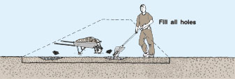
(b) Fill all holes in the foundation area with suitable soil. Use thin layers, wet them if necessary, and compact well. |
|
| (c) Roughly level the surface of the dike's foundations.
|
(d) Compact the whole area well after wetting, if necessary, so that the surface materials of the foundations are as well compacted as the subsequent layers of the dike. |


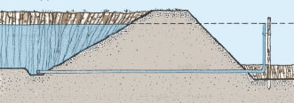
Building a cut-off trench
3. If the foundation soil does not contain an adequate layer of impervious material at the surface, you should build a cut-off trench (sometimes called a puddle trench) within the dike's foundations. Its main purpose is to reduce water seepage under the dike. It will also help to anchor the dike solidly to its foundations.
|
Seepage may cause a dike to slide
 |
A cut-off trench helps to prevent seepage
and sliding
 |
|
Detail of a cut-off trench dug through
a permeable layer of soil into an impermeable layer
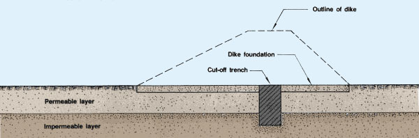 |
4. The size of the cut-off trench increases with the size of the dike. You can use the following guidelines:
- width of the trench: from 0.5 m in small dikes to at least 1 m in larger dikes;
- depth of the trench: preferably extending through the pervious soil layer into the impervious layer beneath. In a large dike for a barrage pond for example, the cut-off trench should reach at least 30 cm into the impervious layer, throughout its entire length. In small dikes, the cut-off trench is at the most 0.6 to 1 m deep, regardless of the position of the impervious layer;
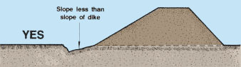
- shape of the trench: sides are dug vertically in small to medium dikes. In larger dikes, the sides should be cut at a 0.5 to 1:1 slope.
|
Cut-off trench for large pond |
Cut-off trench for small pond |


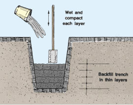
5. To build the cut-off trench, proceed as follows.
(a) Clearly mark the centre line of the dike base, for example with stakes and string.
(b) On each side of this centre line, clearly mark the limit of the cut-off trench to be built.
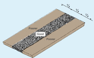
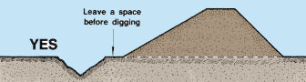
(c) Dig the trench to the depth, width and side slopes required, placing the removed soil material over the foundations of the dike in one-third of the area toward the dry side of the dike. Be careful not to include roots, organic materials or large stones.
(d) Spread this soil material in thin layers and compact it well.
(e) Make sure the trench is dry.
|
|
|


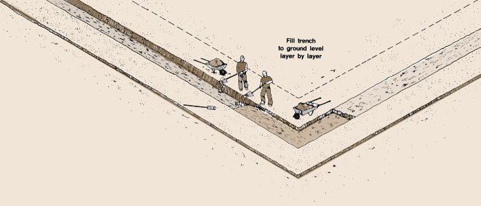
(f) Backfill the cut-off trench to the natural ground surface with soil material of the same quality as for a dike core (see Section 12.2, Soil, 6). Place the backfill material in thin layers, wet it if necessary, and compact well. If clay soil is used, "heel" it into place, or use suitable mechanical equipment.
|
|
 |
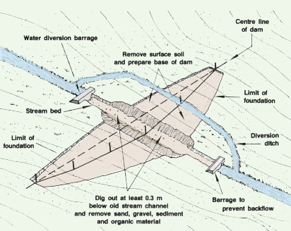
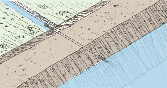
Backfilling a stream channel
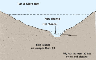
6. If a stream channel crosses the foundations of the dam, such as in the case of a barrage pond, you must prepare the channel of the stream where the dam will be built. If the water is flowing when you want to work on the channel, you will first have to divert the stream.
|
Preparing the stream channel for a barrage
pond |

7. Dig the diversion ditch around the site of the future dam as shown. That way, you will be able to use the same diversion ditch when you build the dam (see Section 6.6, paragraph 9 and following). Then, proceed as follows:
(a) Deepen and widen the channel as necessary to remove all stones, gravel, sand, sediment, stumps, roots and organic matter.
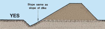
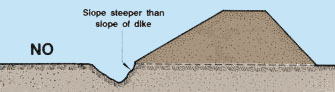
(b) Dig at least 30 cm below the original channel bed or until you reach rock. Make the side slopes of the new channel no steeper than 1:1.
Note: if the soil base below the channel is permeable, it is best to make a cut-off trench.
|
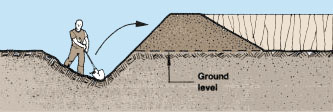
Cross-sections through a future dam site
showing how to clean and enlarge the old stream channel
|
|

6.4 Calculating dike and excavation volumes
1. Before starting the construction of your pond, you should calculate how much soil you will need to build its dikes. Then, you will need to estimate the excavation volume necessary to provide such soil volume. According to the topography of the construction site and the type of pond to be built, you should select the best method to be used. You should estimate expanded and compacted volumes (see Section 6.2), and you should also use standard settlement allowances (see Table 28).
2. Multiply excavation volume by the expansion factor (Table 28) to obtain the expanded volume. This expanded volume is then used in the construction volume of the dike. After compaction and settlement, as estimated by the compaction potential, it should reach the design volume required.
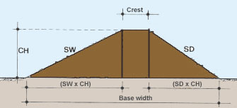
Calculating the width of the dike base
3. Having determined the characteristics of your dikes, determine the width of the dike base (in m) by adding:
- crest width (in m);
- construction height (CH in m) multiplied by slope ratio of dry side (SD);
- construction height (CH in m) multiplied by slope ratio of wet side (SW).
|
Base width = crest width + (CH x SD) + (CH x SW) |
| Note: use the construction height, including the settlement allowance, and not the design height of the dike (see Section 6.1). |
|
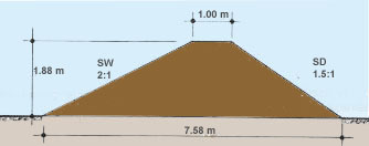
Example
A 0.04-ha pond (400 m2 ) has to be built in clayey soil with dikes 1.50 m high and 1 m wide at the top, according to the design. If SD = 1.5:1 and SW = 2:1, calculate the base width of the dikes.
(a) From Table 28, estimate the settlement allowance of the expanded clay volume (20 percent for medium clay soils).
(b) Consider the design height = (100% - 20%) = 80 percent of construction height.
(c) Obtain the construction height = 1.50 m � 0.80 = 1.88 m.
(d) Calculate dike base width = 1 m + (1.88 m x 1.5) + (1.88 m
x 2) = 1 m + 2.82 m + 3.76 m = 7.58 m.
| Note: see also examples in Table 27. |
|
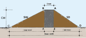
Calculating the cross-section of a dike on horizontal ground
4. The size of the cross-section of a dike on horizontal ground (ABCD in m2) (see diagram) is obtained by adding:
- area ABFE (in m2) = crest width (AB) x construction height (CH);
- area AED (in m2) = ED x (AE � 2)= (SD x CH) x (CH � 2);
- area BFC (in m2) = FC x (BF � 2)= (SW x CH) x (CH � 2).
| CH = the construction height of the dike;
SD = the slope ratio of the dry side; SW = the slope ratio of the wet side. |
|
|
|
Example For the above 0.04-ha pond to be built in clayey soil, calculate the size of the cross-section of the dike as:
|
 |
5. To calculate the cross-section of a dike on horizontal ground with identical side slopes, you can also use Table 29.
|
TABLE 29
|
|||||||||||||||||||||||||||||||||||||||||||||||||||||||||||||
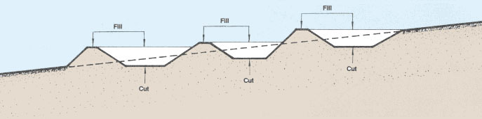
Calculating the cross-section of a dike on sloping ground
6. The cross-section of a dike on sloping ground can be calculated most easily using a scale drawing.
(a) Draw a horizontal line from D, meeting AE at E'.
(b) Draw a horizontal line from C, meeting BF at F'.
(c) Draw a vertical line PO down the centre line of the dike.
(d) Cross-section = ADE + AEFB + BFC = 0.5(AE x DE') + (AB x PO) + 0.5(BF
x F'C).
Note: for ground slopes of less than 10 percent, and where the dike side slopes are the same on each side, you can use the method given for horizontal ground.
Calculating the cross-section of a dike on irregular ground |
||
| 7. The cross-section of a dike to be built on irregular ground can be calculated in two ways. |
Calculating the cross-section of a dike
on sloping
ground using a scale drawing 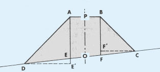 |
|
(a) Draw a straight line D'E'F'C', approximating the shape of the ground, then use the procedure given for sloping ground.
(b) Alternatively, mark the shape out on squared paper, and using the scale, count the squares to obtain the area.
|
Calculating the cross-section of a dike |
Calculating the cross-section of a dike |


Calculating the volume of dikes on horizontal and regular ground
8. To estimate how much soil will be needed for the construction of a dike, you need to know its volume. The calculation method depends on the site topography and on the type of pond to be built.
9. If the topography of the construction site is reasonably flat (less than 0.30 m difference in average site levels) and regular, you can calculate the volume of the dike (in m3) by multiplying the cross-section of the dike(in m2 and halfway along the dike for an average area) by its length measured along the centre line (in m).
|
Example Using the figures from the example on paragraph 4, the cross-section of the dike equals 8.0652 m2. If the length of the dike to be built is 20 m x 4 = 80 m, its volume is 8.0652 m2 x 80 m = 653.216 m3. |
 |
||||||||||||||||||||||||||||||||||||||||
| 10. Alternatively you can calculate the volume
using graphs.
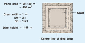
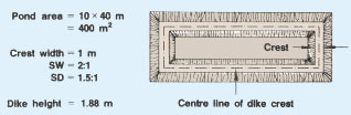
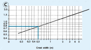
(a) In Graph 3a, enter the area of the pond (in m2) . According to the average construction height of the dikes (in m), find the standard volume (in m) of the dikes for a standard pond where: ratio length:width is 1:1 (square shape); both dike slope ratios are 2:1, crest width is 1 m. (b) If the side slopes of the dike are not 2:1, multiply the standard volume by S (slope factor), according to the table shown at right. (c) If the crest width of the dike is not 1 m, multiply the standard volume by C (crest factor), obtained from Graph 3b. (d) If the shape of your pond is not square, multiply the standard volume by P (pond shape factor), obtained from Graph 3c. |
|
Example
For the previous example, Graph 3a shows a standard volume of 720 m3. As the side slopes are 2:1 (inner) and 1.5:1 (outer), this is multiplied by S = 0.9 to give 720 m3 x 0.9 = 648 m3. (Compare this result with the previous example in which you calculated 653 m3.)
11. If you decide to change the crest width to 0.51 m, from Graph 3b you find C = 0.8. The volume will now be 648 m3 x 0.8 = 518.4 m3
| 12. If the pond was not 20 x 20 m but, for example,
40 x 10 m, then the ratio L:W = 4. From Graph 3c, P = 1.25. With a crest width of 1 m, the volume. of the dikes would then be 648 m3 x 1.25 = 810 m3. |
 |
|


Calculating the volume of dikes on sloping or irregular ground
13. If the topography of the site is more steeply sloping or more irregular, you cannot calculate the volume of the pond dikes just by using one cross-section. There are several possible methods, depending on the type of ground and the accuracy you require.
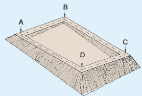
14. With a first group of methods you can calculate the dike volumes by using averages of the dike cross-sections or you could use the average of the cross-sections at the corners of the dike.
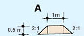
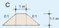
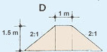
Example
A 400-m2 (20 x 20 m) pond is to be constructed with
wall heights of 0.5 m at corner A, 0.3 m at corner B, 1.1 m at corner
C and 1.5 m at corner D. Crest width is 1 m and side slope 2:1 on both
sides. The cross-section areas at each corner are:
A: (1 m x 0.5 m) + 2 x (0.5 m x 0.5 m x 1 m) = 1.5 m2,
B: (1 m x 0.3 m) + 2 x (0.5 m x 0.3 m x 0.6 m) = 0.48 m2,
C: (I m x 1. 1 m) + 2 x (0. 5 m x 1. 1 m x 2.2 m) = 3.52 m2,
D: (1 m x 1.5 m) + 2 x (0.5 m x 1.5 m x 3 m) = 6.0 m2.
Average area for wall AB = (1.5 m2 + 0.48 m2)
� 2 = 0.99 m2 and volume for wall
AB = 0.99 m2 x 20 m = 19.8 m3.
Similarly:
- for BC, average area = 2 m2 and volume = 40 m3;
- for CD, average area = 4.76 m2 and volume = 95.2 m3;
- for DA, average area = 3.75 m2 and volume = 75 m3.
Consequently, total volume of dikes = 19.8 m3 + 40 m3 + 95.2 m3 + 75 m3 = 230 m3.
|
Average of areas at corners of dike
|
|
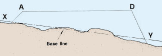
15. Alternatively with rough ground, you could use average dike cross-sections based on an estimated base line, then add the four wall volumes.
|
Example Using the preceeding example, the heights of A and D are estimated by drawing line XY through the base so that the areas above the line are approximately equal to those below the line. Note that the profile of the ground as drawn should represent the average height across the wall base. |
Estimating dike base on rough ground
 |
16. You can also use the graphical method explained earlier (see paragraph 10), using an average height for the four walls of the dike, although this method is less accurate.
Example
Using the graphical method, the average wall height is (0.5 m + 0.3 m + 1.1 m + 1.5 m) � 4 = 0.85 m, and the standard volume, which needs no further correction, is about 180 m3 . This is about 80 percent of the previous figure (see paragraph 14).
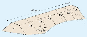
17. For a more accurate measurement of dike volume on rough ground, you should apply the following formula, known as Simpson's rule, where: V = (d � 3) x [A1 + An + 4(A2 + A4 + ... An-1) + 2(A3 + A5 + ... An-2)]. Proceed as follows:
(a) Divide the length of the dike into an odd number n of cross-sections at equal intervals of d metres.
(b) Calculate the area A of each cross-section as explained earlier.
(c) Introduce these values into the above formula.
|
Example The dike is 60 m long. (b) Introduce these values into the Simpson's rule formula:
(c) Calculate V = (10 m � 3) [10 m2 + 12 m2 + 4(16 m2 + 11 m2 + 10 m2 + 2(18 m2 � 8 m2)] = 740 m3. |
Calculating dike volume by cross-sections
 |
|
Calculating the volume of a dam for a barrage pond |
||
| 18. If you have to calculate the volume of the dam to be built for a barrage pond, one of the above methods can be applied. However, because of the presence of the stream channel and numerous changes of ground slopes, it is usually necessary for precise estimates either to measure cross-sections at small d intervals or to subdivide the dam into sections using different d intervals. (For a more rapid but less precise estimate, see Section 11.3, Topography) |
Cross-sections to be calculated for a barrage
dam
 |
|
Calculating volumes of excavated material
19. You will need to know excavation volumes for:
- topsoil;
- borrow pits, dug near an earth structure to provide the material for its construction;
- excavated ponds, to provide the pond volume required;
- other structures such as harvest pits, supply channels, etc.
| 20. You will normally have to remove the topsoil before you reach soil good for construction material. Levels should therefore be taken from the base of the topsoil layer. In most cases, the sides of the excavation should be sloped to prevent them from collapsing. In many cases (ponds, channels, etc.) these will be of specified gradients. |
 |
||
|
21. For reasonably flat, level surfaces, where excavated width is at least 30 times the depth, volume of excavation can be estimated as:
|
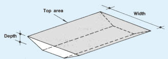 |
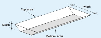
22. Where the width is less than 30 times the depth, you should correct for side slopes as follows:
|
V = [(top area + bottom area) � 2] x depth. |
Example
A 400 m2 (40 x 10 m) area is to be excavated, 1 m deep, with side slopes 2:1. As the width (10 m) is less than 30 times the depth (30 x 1 m), the first method is not accurate (estimated volume would be 400 m2 x 1 m = 400 m3).
| Use the second method, where top area = 400 m2 and base area=base length x base width. Base length = 40 - (2 x slope x depth) = 40 - (2 x 2 x 1 m) = 36 m Base width = 10 - (2 x slope x depth)= 10 - (2 x 2 x 1 m) = 6 m Base area = 36 m x 6 m = 216 m2 Average area = (400 m2 + 216 m2)� 2 = 308 m2 Volume therefore = 308 m2 x 1 m= 308 m3. |
 |
23. On gently sloping ground, calculate the cross-section at each end of the excavation. Then:
(a) Calculate the average cross-section of the excavation.
(b) Multiply by the average length of the excavation.
|
Example If the area is on a gentle slope, calculate cross-sections at AB and CD, and average length. |
Calculating volume of excavation by cross-sections
 |
|
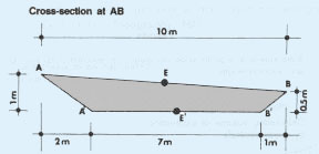
| (a) Cross-section at AB can be determined by
drawing out on squared paper, or estimated by: [(AB + A'B') � 2]
x average depth, or [(10 + 7) � 2] x [(1 + 0.5) � 2] = 8.5 m x 0.75 m = 6.375 m2. |
 |
|
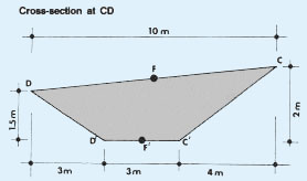
| (b) Cross-section at CD, similarly = [(10 + 3)
� 2] x [(2 + 1.5) � 2] = 6.5 m x 1.75 m = 11.375 m2.
(c) Average length can be determined at the midpoint. (d) Thus volume = average area x average length = |
 |
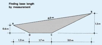
24. On more steeply sloping ground (steeper than 10 percent in any direction), you can use the same method as above; however, the lengths of the base and the corresponding cross-sections, as calculated in the previous method, will not be sufficiently accurate. To obtain a reasonable estimate proceed in the following way.
| (a) Use squared paper and obtain the base length by measurement. Then use this base length in the calculations, as shown earlier. |
 |
|
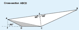
| (b) For best accuracy, calculate cross-section
ABCD = area ADC + area ABC = [(FC x AF) � 2] + [(EC x AB) � 2] |
 |
25. With particularly uneven surfaces, you can use one of the following methods.
- Estimate the surface level by averaging the elevations of specific points of the surface, and then calculating the crosssections as above.
- For a more accurate result, use Simpson's rule with a series of cross-sections (see paragraph 17 in this section).
- Set up a grid over the area and calculate the volume (in m3) either section by section, or by noting the elevation of each grid crossing point (in m) and using the formula:
|
Volume = [(A� 4) x (sum of the elevation of single points)]
|
where A is the area of each grid square in m2.
Example
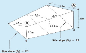
In the case shown, relative elevations are marked on a grid made of 10 x 10 m squares so that the area of grid squares A = 10 x 10 m = 100 m2. According to the formula:
Volume = (100 m2 � 4) x [(3.1 m + 2.0 + 2.6 + 2.0 + 3.1) + 2(2.6 m + 3.5 + 3.0 + 2.0 + 3.5 + 2.5 + 1.8 + 2.0) + 3(2.8 m) + 4(3.1 m + 2.1 + 2.5)] = (100 m2� 4) x [(12.8 m) + 2(20.9 m) + 3(2.8 m) + 4(7.7 m)] = (100 m2 �4) x (93.8 m) = 2 345 m3.
Note: you will normally have to correct this volume for the side slopes.It is usually easier to make these adjustments outside the grid, calculating the additional volume either square by square or by averaging along each side of the grid.
|
Example If in the above example, a side slope ratio of 2:1 is used, the additional volume can be estimated in two ways. (a) Estimating square by square: At the first square (Section AB) for example:
(b) Estimating by averaging along each side. For side AC for example:
|
Relative elevations
 |
|
|
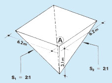
26. To estimate the volume at each corner, use the formula: V = 0.33 x h x S1h x S2h, where h = depth of excavation (in m) at the corner and S1, S2 are the side slopes. |
 |
|
|
Example In the previous case, at corner A for example, if side slopes
on both side and end are S1 = S2 = 2:1,
volume of corner cut If the end slope had been 3:1 and the side slope 2:1, then
volume |
 |
Remember: with any calculations for building and excavation, do not use methods that are more precise than you require. Because of the difficulty of predicting expansion and compaction accurately, volume estimates in practice are generally only accurate to within 10 percent. There is usually therefore little point in being more precise than this, and so there is no need to allow for every little irregularity or slight change in slope.
6.5 Constructing dug-out ponds
1. Dug-out ponds, entirely obtained through soil excavation, are the simplest to build. There are two main types of dug-out pond depending on the water supply (see Section 1.4):
- dug-out ponds fed by rain and surface runoff, commonly found in relatively flat, well-drained terrain such as the low point of a natural depression;
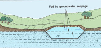
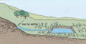
- dug-out ponds fed by springs or seepage, the latter being commonly found in areas where the ground water table is close to the surface, either permanently or seasonally.
|
An example of seepage dug-out ponds
Note: see also Section 1.7, item 8 for a larger illustration of seepage dug-out ponds in a valley bottom |
Kinds of dug-out ponds
 |
|
 |
 |

Selecting soil for dug-out ponds
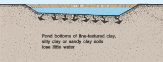
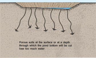
2. To build a rain-fed dug-out pond, it is essential to have enough impervious soil at the site to avoid excess seepage losses. The best sites are those where fine-textured clays and silty clays extend well below the proposed pond depth. Sandy clays extending to adequate depths are satisfactory. Avoid sites with porous soils, either at the surface or at the depths through which the pond would be cut.
|
|
|
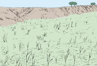
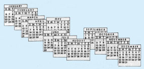
3. To build a seepage dug-out pond, look for soils where the waterbearing layer is thick enough and permeable enough to provide the required water. It is best to observe the site during a complete annual cycle to check on the possible variations of the water table elevation with the season.
|
Site before construction |
Check water table variations on the site
for one year |
Building a dug-out pond
4. Begin building the dug-out pond by preparing the site as follows.
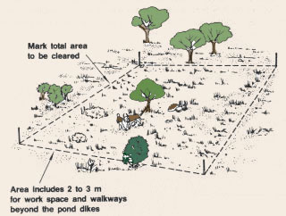
|
(a) Mark the area to be cleared using stakes. This should include the total area of the pond to the outside limits of the pond dikes and, in addition, an area of two to three metres to serve as a work space and for walkways beyond the dikes.
|
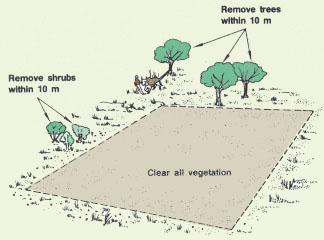
(b) Clear all vegetation from the marked area (see Chapter 5). Also remove all shrubs and trees within 10 metres of the cleared area.
|
|
|
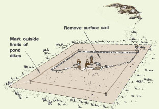
(c) Next, at the very centre of the cleared area, mark the pond area to the outside limits of the pond dikes using heavy string or cord. Remove the surface soil from this area and store it for later use.
|
(d) Now mark the inside limits of the pond bottom
using heavy string or cord. Do this on
the basis of the selected side slopes (see Item 13, Section
6.1). |

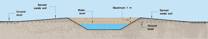
(f) There are two easy ways to dispose of waste soil material and to prevent it from tumbling or eroding back into the dug-out pond:
- if there is enough space around the pond, you can spread the
waste soil there.
Limit the thickness of spread soil to 1 m at most and slope it gently away from the pond;
|
|
- make a pile of waste soil near the pond, but be sure
to leave at least 4 m between the toe of the pile and the pond.
The sides of piled soil should have a gentle slope of 3:1 or more.
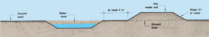 |
Note: you can use a pile of soil as a windbreak or for the cultivation of a crop (see also Section 5.6).
(g) Clearly mark the limits of the areas where the excavated material
will be spread or piled.
(h) Dig to the designed depth within the limits of the pond, cutting
the sides vertically. Transport the waste soil to the planned
areas.
Note: usually the pond bottom in drainable ponds is given
a one-percent slope between the inlet and outlet ends; in undrainable
ponds, the pond bottom may be horizontal. You can calculate the volume
of the material to be excavated using one of the methods in the previous
section.
|
Disposing of waste soil material
|

|
|

(i) Shape the sides of the pond to the desired slope and finish the pond bottom and the horizontal dike tops. Remove any excess soil.
|
|
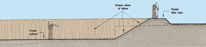
(j) Bring back the surface soil to cover the waste material and the dike tops. Then plant or sow grass all around the pond to prevent erosion (see Section 6.9).
|
|

Note: water control structures such as a feeding canal, inlet pipe, outlet sluice, spillway or drainage canal may be provided for dug-out ponds (see later).
6.6 Constructing barrage ponds
1. Barrage ponds are embankment ponds formed by a dam, which is built across a narrow valley to impound water behind it (see Sections 1.3 and 1.4).
Note: in this manual, for barrage ponds you will learn how to build small dams only, their height being limited to 2.50 m. If you need to build a higher dam, you should consult a specialized engineer.
2. As the height of the dam increases, the need for sound foundations becomes essential. The best foundations consist of a thick layer of relatively impermeable consolidated clay or sandy clay, at shallow depth. Never build a dam over rock or sand. Whenever in doubt, ask for advice.
Obtaining the soil material for construction
4. In order to reduce the distance the soil needs to be transported, try to dig the soil necessary for the construction of the dam from an area close by, for example:
- from the edges of the valley;
- from inside the pond.
5. An area from which soil is taken is called a borrow pit. Be careful to keep the limit of any borrow pit at least 10 m from the wet toeline of the dam. Plan the drainage of this area to be included within the barrage pond, for example using a trench toward the water outlet.
|
|

Staking out the base of the dam and setting out the earthwork
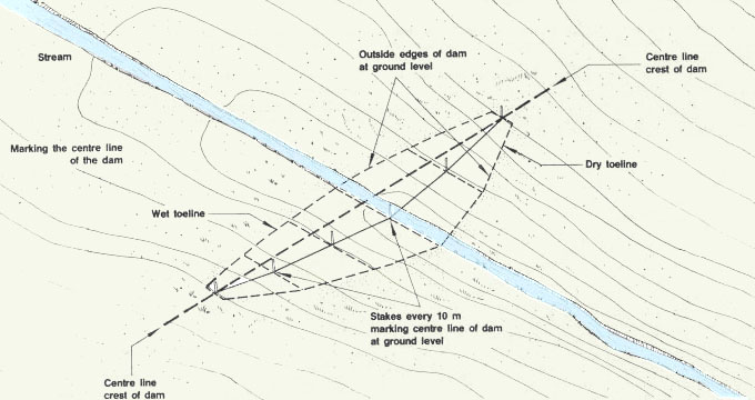
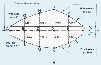
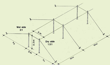
6. Clearly mark the centre line of the dam at ground level with tall stakes and a line. It is usually perpendicular to the main axis of the stream in the valley to be flooded.
7. Calculate distances from the centre line to the two toelines on a series of perpendiculars set out at regular intervals as:
| (dam crest width � 2) + (dam construction height x slope ratio). |
Note: the design height of the dam at each point along the centre line is obtained from your topographical survey of the valley cross-section at this point. From these design heights, calculate the construction heights (see Section 6.1).
|
|
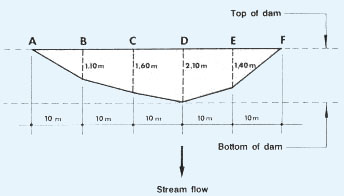
Example
You plan to build a dam with maximum design height DH = 2.10 m, crest width = 2 m, wet slope 2:1 and dry slope 1.5:1.
Soil settlement allowance is estimated at 15 percent. The valley cross-section along the centre line of the dam can be sketched as shown, giving the design heights DH(A), DH(B) ... at points A, B ... at 10-m intervals along the centre line.
Calculate the distances from centre line AF to toelines GHIK and LMNO as follows:
|
8. Stake out on the ground points G, H, I, K on the wet side and L, M, N, O on the dry side of centre line AF. These points show you what the outside limits of the dam base should be.
|
|
|
Preparing for the construction of the dam
9. Divert the stream to a site as close as possible to one of the valley sides and well away from the original stream bed (see section 6.3, paragraph 6). This task will be much easier if you have scheduled the construction work to coincide with the dry season.
10. To prepare the foundation of the dam, clear the base area, remove the surface soil and treat the surface of the foundations, giving particular attention to the old stream channel (see Section 6.3) and to the sides of the valley, according to the quality of the foundations' soil:
|
|
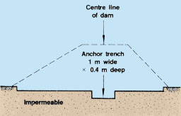
11. If the soil is impermeable, dig an anchoring trench (about 1 m wide and 0.4 m deep) along the centre line of the dike base to anchor the dike to its foundations. Refill this trench with good clayey soil and compact it well. Extend the trench sideways, well into the sides of the valley;
12. If the soil is permeable, build a cut-off trench (at least 1.5 m wide) along the centre line of the dam (see Section 6.3), which will also assist in anchoring the dam to its foundations. Extend the trench sideways, well into the sides of the valley
 |
|

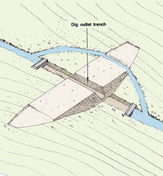
13. Build the water outlet structure(s), as necessary (see later chapters). Preferably, place it (or them) out of the stream bed, at a point to be dug lower than the lowest point in the pond.
Note: if the dam is to be constructed by machine, for example a bulldozer, the outlet structure could be built later.
14. Clearly mark the construction height of the dam and the crest width (refer to centre line) with stakes and lines, on the basis of planned dam characteristics (see Section 6.1). Maximum height is at the lowest point of the valley. Check the limits of the future pond upstream.
15. Set out the dam earthwork using templates at intervals of 25 m or less and clearly showing the slopes of the sides. You can also use strings. If you use machinery, it is best to establish an auxiliary base line outside the radius of operation of the machinery, based on topographical survey bench-marks.
|
Stakes and lines to mark construction height
|
|
Wood templates to mark construction height
|

Building the first part of the dam |
||
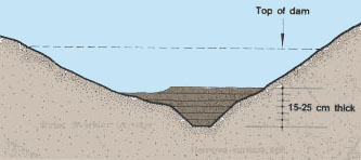
| 16. Start building the dam by laying out successive horizontal layers 15 to 25 cm thick. Work across the entire site, from one side of the valley to the new stream channel, and from the wet to the dry side of the dam. Wet the soil if necessary and compact each layer well (see Section 6.2). |
Build up dam using horizontal layers
|
|
17. According to the availability of clayey soil, you will use either homogeneous soil layers as wide as the dam or heterogeneous soil layers, each kind of soil covering only part of the dike width. Clearly mark the limits to be followed with stakes and lines.
(a) If there is enough good soil from which to build the entire dam, proceed by placing layers to cover the full base width.
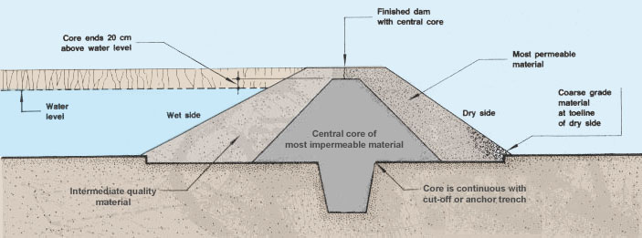
(b) If the supply of good soil is limited, use it only to build a central core with the following characteristics:
- width: about one-third of the width of the dike;
- side slopes: at least a ratio of 1.5:1;
- height: water depth plus 20 cm.
Note: this core should be continuous with either the cut-off trench or the anchoring trench built in the foundations of the dam (see earlier) and should be properly placed and compacted.
|
Build each layer of good quality soil
|
If you do not have enough good soil to
build the entire dam, |

Note: do not place heaps of soil next to each other without spreading them into a continuous layer before compaction
(c) If you have to use various types of soil to build the dam, use the most impermeable material as a central core. Place the most permeable material on the dry side of the dam. Place the intermediate quality material on the wet side of the dam. Adjust each side slope to the particular kind of material used.
(d) If you do have relatively permeable materials on the dry side of the dam, it is useful to place larger grades (such as medium to coarse gravel or small rocks) at the dry toeline. This acts as a filter and prevents seepage water from washing out the finer dike material.
Beware: you should pay particular attention to the compaction of the soil placed around the water outlet structures. Use good soil, the right moisture content, thin soil layers and thorough, strong tamping.
 |
|
A typical barrage pond built in two parts
|
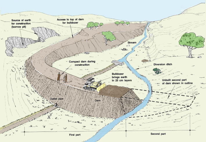
| 18. To build up the dam, you
can use hand labour or machinery. If you use machinery
such as a bulldozer for pushing, spreading and compacting the
soil material, you could proceed in the following way.
(a) Build up the first part of the dam to about 1 m above the level of the foundations, progressing layer by layer. (b) Determine and stake out the centre line of the water outlet structure, perpendicular to the centre line of the dam. |
Building a dam for a barrage pond
 |
|
|
(c) Mark a parallel line on each side of this outlet centre line at a distance of about 0.5 m. (d) Dig a trench about 1 m wide, down to the planned elevation for the water outlet pipes. |
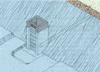
 |
|
Building a water outlet structure in the
outlet trench |
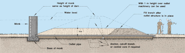
(e) Build the water outlet structure (see chapter 10), being careful to make proper reinforcements around the areas where the water flows in and out of the structure.
(f) Refill the trench and compact it well, rebuilding the dam section as it was before. Pay particular attention to the central core if you have built one. Check carefully the quality of compaction around the water pipes. If possible use antiseepage collars.
(g) Proceed with the building of the dam as before. The water pipes are now well protected by 1 m of earth, and they will not collapse under the weight of the bulldozer.
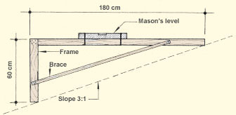
19. When you reach the planned contruction height for the dam, carefully
begin to form the two side slopes. Use slope gauges to assist you in
cutting each slope at its planned angle.
|
A slope gauge |
60 cm vertical by 180 cm horizontal gives a slope of 3:1
|
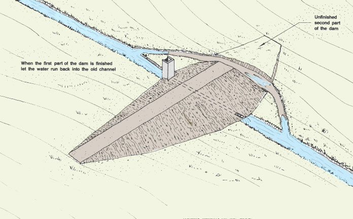
Note: it may be necessary to build a spillway and an emergency spillway (see Sections 11.3 and 11.4).
20. When the first part of the dam is completed, let the stream run back into its old channel and through the water outlet structure. You are now ready to finish your barrage pond.
Note: if the dam is to be built using machinery, aim to make slopes that are slightly steeper than the planned slope, as mechanical grading usually flattens off the slope.
|
|
Finishing the barrage pond
21. Repeat the previous operations for the second part of the dam in the area where the stream was diverted temporarily, but first fill the bed of the diversion ditch within the pond area.
(a) Prepare good foundations, extending them sideways well into the side of the valley. Be particularly careful to make a good foundation in the bed of the stream diversion.
(b) Set out the dam earthwork properly.
(c) Build up the second part of the dam, being particularly careful to connect it strongly to the first part of the dam and well into the side of the valley.
(d) Form the two side slopes.
|
|

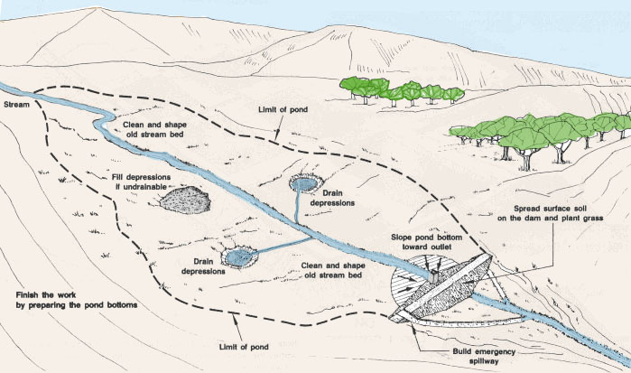
22. Work on the bottom of the pond to make sure the pond is completely drainable.
(a) Tidy up and shape the course of the old stream bed.
(b) Build a regular slope toward the water outlet and dig bottom drainers (see Section 6.10).
(c) If there are depressions, dig a draining trench toward a lower part of the pond bottom. This is important if you have borrowed the soil from within the pond area.
(d) If necessary, fill any undrainable depressions.
23. Finish your barrage pond by taking back some surface soil, spreading it on the dam and planting grass (see Section 6.9).
|
|
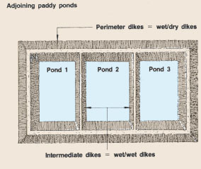
6.7 Constructing paddy ponds
1. Paddy ponds are embankment ponds built over flat ground. They have four dikes of approximately equal height. The size of the dikes, and thus the volume of earthwork, is usually limited to the minimum because of the need to import the soil material or to find it near the site.
Note: whenever the soil to build the dikes is taken by reducing the level across the whole pond floor, the resulting pond will be considered a cut-and-fill pond built on horizontal ground (see Section 6.8).
|
|

2. In some cases earth to build paddy ponds can be taken from areas
next to the dikes, either inside or outside the pond, thus reducing
construction costs. Trenches for dike material should not be cut with
side slopes steeper than the dike itself.
|
Building the dikes using soil material
|
Building the dikes using soil material
from the site
|
|
|
How to remove soil material close to the
dikes |
|
|
 |
 |

Staking out the base of the dikes
3. Clearly mark the centre line of each of the four dikes; the shape of the pond is usually either square (minimum earthwork) or rectangular, and the four centre lines will meet at right angles (see Section 3.6, Topography).
4. On each of the centre line stakes, indicate the level corresponding to the construction height CH of the dike to be built. Determine the level using one of the levelling methods described in Topography.
5. According to the characteristics of your dikes, calculate the width at each part of the dike base on either side of the centre line, as equal to: (crest width � 2) + (CH x side slope)
|
Topographical devices for levelling
|

 |
|
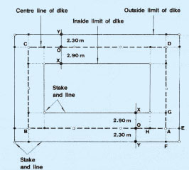
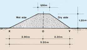
Example If the crest width of dikes = 1 m, construction height
= 1.20 m, wet side slope = 2:1 and dry side slope = 1.5:1, then
at corner A distances AG and AH = (1 m � 2) + (1.2 m x 2) =
0.5 m + 2.40 m = 2.90 m; distances AE and AF = (1 m� 2) + (1.2
m x 1.5) = 0.5 m + 1.80 m = 2.30 m; and similarly all around
the pond area for the other corners B, C and D.
|
Cross-section of dike |

Preparing for the construction of the dikes
7. When the inner and outer limits of the pond have been staked, clear any remaining vegetation from the area.
8. Remove the surface soil only from the area of the dike bases, as staked out above, and store it close by (see Section 5.6).
9. Treat the surface of the foundations of the dikes (see Section 6.3).
|
|
10. According to local soil quality, build either an anchoring trench or a cut-off trench (see Section 6.3) along the centre lines of the dikes.
11. Build the water control structures, as necessary (see later chapters ). Place the outlet entrance at an elevation low enough to ensure complete drainage of the pond along the sloping bottom (see paragraph 14 of this section).
|
Water control structures
|
||
|
Pipe inlet
 |
Stand-pipe outlet
 |
|
|
Earthen canal inlet
 |
Monk outlet
 |
|
Building the dikes of a paddy pond manually |
||
|
12. There are several ways to build the dikes of a paddy pond.
To construct them manually, you can use templates as for the barrage
pond, although here only one template size is required. Note: you can also use stakes and lines to mark construction height as shown in section 6.6, para.15. |
Wood templates to mark construction height
 |
|
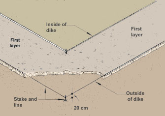
13. Another way to build the dikes of a paddy pond is given here.
(a) Lay out a line to join and clearly mark the stakes setting out the inside limits of the dike's base. Attach this line at a height of about 0.20 m above the level of the surface of the dike's foundations.
(b) Similarly lay out a line at the same level, joining the stakes setting out the outside limits of the dike's base.
(c) Build the first layer of the four dikes 0.20 m high, bringing in good soil, placing it between the two strings all around the pond area, spreading it well, wetting and mixing it if necessary and tamping it thoroughly, especially around the outlet structure.
(d) For each dike, move the inside limits of the dike base (stakes and lines) toward the centre line of the dike by a distance equal to 0.20 m x side slope; similarly, move the outside limits by a distance equal to 0.20 m x dry slope.
|
Building a dike layer by layer
 |
 |
|
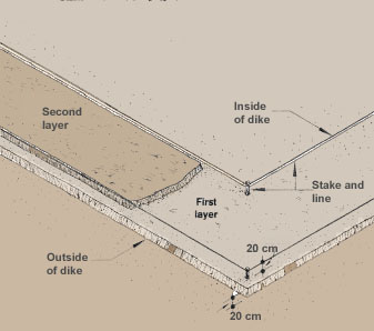
Example If wet slope is 2:1 and dry slope is 1.5:1, move the inside limit by 0.20 m x 2 = 0.40 m and the outside limit by 0.20 m x 1.5 = 0.30 m. (e) Raise all the lines 0.20 m higher. (f) Build the second layer of the four dikes 0.20 m high between these new limits, as you did for the first layer. (g) For each dike, move the inside and outside limits toward the centre line by the same distances as previously. (h) Raise all the lines 0.20 m higher again. (i) Build the next layer of the four dikes 0.20 m high between these new limits. Repeat these last three steps until you reach the level of the top of the dikes as indicated on the centre line stakes. It may be that the last soil layer is less than 0.20 m thick, in which case adjust the level of the lines with the level of the top of the dike. Note: if you need to build a central core within the dikes, you should add lines setting out its width on either side of the centre line. The core is built together with the rest of the dike, using different types of soil for each 0.20-m layer. |
 |
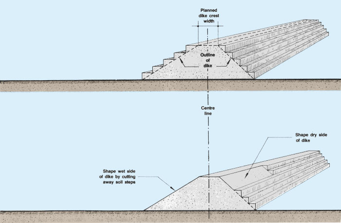
Finishing the dikes
14. Now the dikes are built with sides that look like staircases. To reform these dikes with smooth side slopes and to finish their construction, proceed in the following way.
(a) On the top of each dike, set out the planned dike crest width, measuring half of its value on either side of the centre line and marking the limits with wooden pegs and lines.
(b) Starting from the top of the dike, obliquely cut the end of each soil layer on the wet side of the dikes following a slope that joins the limit of the dike crest to the bottom limit of the layers, until reaching the staked-out limit of the dike base.
(c) Repeat this cutting on the dry side of the dikes.
(d) Transport the soil removed, as necessary.
(e) Remove all stakes and lines.
 |
(f) Bring back some of the surface soil on the top of the dikes and on the dry sides.
(g) Seed or plant grass to control erosion (see Section 69).
|
Cover top and dry sides of with surface
soil
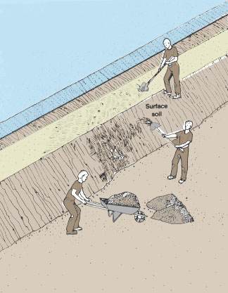 |
Seed or plant grass on top of dike and
on both sides to the water's edge  |
Building bottom slopes and drains for paddy ponds
15. The bottom of the pond now has to be finished; which is done using a levelling survey (see Section 11.4, Topography, 16).
16. For smaller ponds, give the bottom of the pond a gentle slope (0.5 to 1 percent) from the water inlet to the water outlet to ensure easy and complete drainage of the pond.
 |
|
Note: you should always ensure that the entrance of the water outlet structure is at an elevation slightly lower than the lowest point of the bottom of the pond.
| 17. For larger ponds it is best to ensure complete drainage through a network of shallow drains each with a slope of 0.2 percent (see Section 6.10), rather than trying to build a slope over the entire pond area. |
Bottom drains (slope 0.2%)
 |
|
| 18. For ponds where internal trenches have been dug to provide material for dikes, these trenches should be connected together and shaped so as to drain toward the water outlet. |
Internal trenches (slope 0.2%)
 |
Building the dikes of a paddy pond using machinery
19. When using machinery to build the dikes, a method similar to the one for barrage ponds can be used (see Section 6.5), except that four dikes are progressively built up instead of only one.
20. It is best to establish an auxiliary base line with temporary bench-marks from which to set out the earthwork. This base line should be established outside the operation radius of the machinery.
21. If the water outlet structure is built first, all pipes should be protected by a layer of earth at least 0.60 m thick to keep it from collapsing under the weight of the machinery.
Note: if a central core, an anchor or a cut-off trench is required, adapt the size(s) to the size of the dike.
|
Protecting the outlet pipe with a layer
of earth |

Building a series of adjoining paddy ponds |
||
|
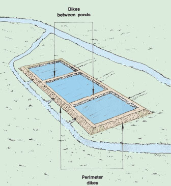
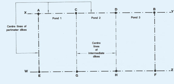
22. When building a series of adjoining paddy ponds, remember that only the dikes forming the perimeter of the pond series should be built with the characteristics of wet/dry dikes. The intermediate dikes, which are wet on both sides, can usually be built less strongly, even without a central core if necessary. 23. First stake out the centre line of a series of perimeter dikes, for example XY for dikes ACDB. Then stake out the centre lines of the opposite perimeter dikes EGHF and the perimeter or intermediate dikes AE, CG, DH and BF. 24. Build the dikes as explained earlier in this section, either manually (see paragraphs 13 and 14) or mechanically (see paragraphs 19 to 21). |
 |
|
|
Stake out centre lines of dikes |
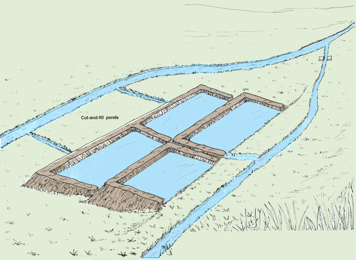
6.8 Constructing cut-and-fill ponds
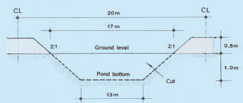
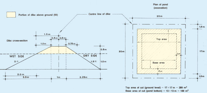
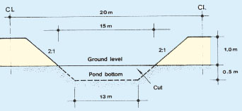
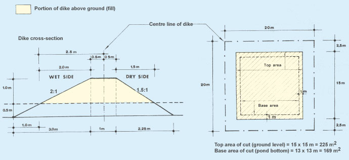
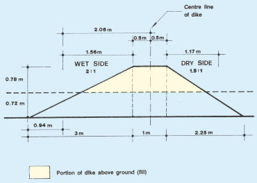
1. In cut-and-fill ponds, at least some part of the pond dikes is made up by the natural ground, cut according to the planned side slope. Normally, a certain volume of soil necessary to build the dikes above ground level is obtained by digging a similar earth volume from inside the pond area, so as to obtain a pond with the planned depth (see below cross-sections showing examples of earthwork in cut-and-fill ponds). The height of the dikes to be built is no longer equal to the depth of the pond, as in paddy ponds.
Note: cut-and-fill ponds are generally of the diversion type, water-fed either from a natural water body or from pumped groundwater.
|
|
|
Examples of earthwork in cut-and-fill ponds
|
Four-dike pond |
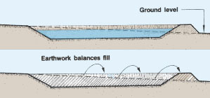

Balancing cut-and-fill on horizontal ground
2. During the planning stage, you must calculate how deep the pond should be dug to have enough soil material to build the four dikes and to create a pond with the planned depth. In good soils, this is usually done by matching the quantity of earth dug to the quantity needed to build the dikes. This is called balancing cut-and-fill. On horizontal ground, two methods can be used for determining the balance of cut-and-fill.
3. In method one, excavation (cut) and dike (fill) volumes are calculated and approximately balanced by trial and error using a graph, as shown in the examples below. In method two, the balancing cut is determined using a graph and tables. Corresponding balancing volumes are then calculated, as described and shown in the example.
4. In practice there is no need for great accuracy, as it is not practical to control depths, heights and slopes with great precision. There will also be additional small volumes to allow for in making pond shapes and allowing space for inlets and outlets, access points, etc.
|
5. To illustrate method one we will use a 400m2 pond (20 x 20 m along the centre lines of the dikes) with 2:1 inner slopes and 1.5:1 outer slopes, a dike construction height of 1.5 m and a crest width of 1 m. Pond area = 20 x 20 m = 400 m2 |
 |
METHOD 1
First trial calculations
Example
If digging depth = 1 m, dike height = 1.5 m - 1 m = 0.5 m. Using the methods described in Section 6.4 obtain:
- cross-section of dike = (1 m x 0.5 m) + [(1 m x 0.5 m) � 2] + [(0.75 m x 0.5 m) �2] = 0.50 m2 + 0.25 m2 + 0.1875 m2 = 0.9375 m2;
- Fill = total dike volume = 0.9375 m2 x 80 m = 75 m3;
- average area of cut = [(169 m2 + 289 m2) � 2] = 229 m2;
- Cut = excavation volume = 229 m2 x 1 m = 229 m3.
In this case, the cut volume greatly exceeds the fill volume.
|
Pond cross-section |
|
|
METHOD 1
Second trial calculation
Example
Use higher dikes and reduce digging depth, say to 0.5 m; thus dike height = 1 m. This time, you obtain:
- Fill = total dike volume = 2.75 m2 x 80 m = 220 m3
- Cut = excavation volume 197 m2 x 0.5 m = 98.5 m3.
In this case, the fill volume exceeds the cut volume.
The correct digging depth lies somewhere between 1 m and 0.5 m, the
two values tried above.
|
Pond cross-section |
|
|
METHOD 1
Estimating correct digging depth
Example
To estimate the correct digging depth, use a simple two-way graph (see Graph 4). Plot the excavation (cut) and dike (fill) volumes for trial 1 (points A and B) and trial 2 (D and C) respectively. Join AD and BC. The intersection E gives the digging depth required (0.72 m) and the approximate balancing volume (155 m3).
You can check these results with a third set of calculations,
where digging depth = 0.72 m and dike height
1.50 m - 0.72 m = 0.78
m:
- total dike volume = 1.845 m2 x 80 m = 147.6 m3
- excavation volume = 210.6 m2 x 0.72 m = 151.6 m3.

6. Now let us look at method two, determined by using a graph and three reference tables.
7. This method is quick, but it is less accurate than method one. In addition, method two does not directly calculate the balancing volumes, although these can easily be calculated once the balancing cut is known. Proceed as follows.
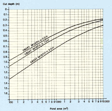
METHOD 2
(a) In Graph 5 enter the area of the pond (in m2) . According to the width of the dike crest (in m) find the balancing cut depth (in m) for a standard pond where:
- the ratio of length to width is 1:1 (the pond is square);
- both dike slope ratios are 2:1;
- pond dikes are 1.5 m high.
(b) If the side slopes of your dike are not 2:1, correct the standard cut depth by S (in m), according to the first table given below.
(c) If the shape of your pond is not square, multiply the cut depth by P, using the second table given below.
(d) If the height of the dikes is not 1.5 m, multiply the cut depth by D, using the third table given below.
|
GRAPH 5 |
|
Example Again using a pond 20 m square (area = 400 m2)
with dikes 1.5 m high and a crest width of 1 m, from Graph 5 determine
a standard cut of 0.75 m. If the pond had not been square, for example L = 28.5 m and W=14 m, you should have found, from the second table, P = 1.04 and corrected the cut depth as 0.70 m x 1.04 = 0.728 m. |
Pond area = 20 x 20 m = 400 m2
Crest width = 1 m SW = 2:1 SD = 1.5:1 Dike height = 1.5 m 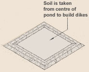 |
If the height of the dikes had been 2 m for example, you should have found, from the third table, D = 1.5 and corrected the cut depth further as 0.728 m x 1.5 = 1.092 m.
|
REFERENCE TABLES
|
|||||||||||||||||||||||||||||||||||||||||||||||||||||||||||||||||
|
1. Correction factor S
|
2. Correction factor P
|
3. Correction factor D
|
|||||||||||||||||||||||||||||||||||||||||||||||||||||||||||||||
Balancing cut-and-fill on sloping ground
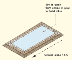
8. On regular sloping ground, the material needed for the dikes is also obtained from inside the pond area, but here both the height of the dikes above ground level and the digging depth vary according to the slope angle. This usually determines the position of the pond and hence the balancing depth.
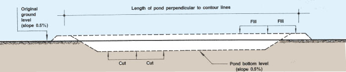
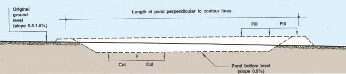
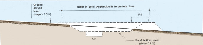
9. If the ground slope is 0.5 percent at the most, the site can be considered horizontal. If the pond is built with its length perpendicular to the contour lines and if dug to the same depth all round, the bottom of the pond will naturally have a 0.5 percent slope at the most.
|
Digging ponds on sloping ground |
10. If the ground slope is from 0.5 to 1.5 percent, the pond should also be built with its length running across the contour lines, but the height above ground level of the two longer dikes will vary from one end to the other. Similarly, the width of these dike bases also varies. The downslope dike will be the highest above ground level, and the upslope dike will be the lowest above ground level. Digging depth is the reverse: it is greatest at the upslope end, least at the downslope end.
|
|
11. It the ground slope is greater than 1.5 percent, the pond should be built with its length running along the contour lines. The height above ground level of the two shorter dikes will vary from one end to the other. Similarly, the dike base width also varies. The longer dike downslope will be the highest above ground level. The longer dike upslope will be the lowest above ground level. Digging depth is the reverse: greatest in the upslope part of the pond, least in the downslope part.
|
|
12. To obtain a rapid estimate with any slope values, you can use either of the previous two methods.
(a) Method 1, the trial-and-error method, uses the volume calculations for horizontal ground with average ground level and average dike height figures.
(b) Method 2, for horizontal ground, uses average ground level and average dike height figures.
Note: these methods are accurate enough when the slope is less than 0.5 percent.
13. To obtain a better estimate of the balancing depth of cut in more steeply sloping ground (more than 0.5 percent) you should use Method 1 together with the methods for calculating excavation and dike volumes on sloping ground.
14. The details of this procedure will vary according to the ground slope.
15. On gentle slopes (0.5 to 1.5 percent), you will have different types of dike:
- one low shorter dike, upslope, either horizontal or varying in height;
- one high shorter dike, downslope, either horizontal or varying in height;
- two longer dikes, varying in height.
|
|

Notes: In ponds A and C, all of the dikes vary in height. In pond B, the short top and bottom dikes are level and the long side dikes vary in height
16. Apply Method 1 in the following way.
(a) Select a first minimum depth of cut measured at the lower end of the pond; calculate excavation volume using the method described in Section 6.4, paragraph 23.
(b) Calculate the corresponding dike volume using the method described in Section 6.4, paragraph 14.
(c) Plot these values on the two-way graph (see Graph 4).
(d) Select a second minimum depth of cut and calculate excavation and dike volumes similarly.
(e) Again, plot these values on the two-way graph (see Graph 4).
(f ) Join the points A to D and C to B and mark the intersection point E. This will determine the balancing minimum cut and the corresponding dike volumes.
17. For ground slopes greater than 1.5 percent, you will have:
- one low longer dike, upslope, either horizontal or varying in height;
- one high longer dike, downslope, either horizontal or varying in height;
- two shorter dikes, varying in height.
18. Select minimum depth of cut and calculate dike volumes accordingly. Complete the trial-and-error procedure using Method 1 for sloping ground as just described.
|
Typical pond positions with steep slopes
(greater than 1.5%) |

In ponds A and B, all of the dikes vary in height
In pond C, the long top and bottom dikes are level and the short side dikes vary in height
The lower ends of ponds A and B face in opposite directions, because of their angled position on the contour
Estimating the cut-and-fill volumes on irregular ground
19. If the construction site of your pond is characterized by irregular slopes and uneven ground, the problem of balancing cut-and-fill earthwork volumes becomes much more complicated. According to the extent of the earthwork involved, rough estimates may be obtained by using Method 1 with volumes calculated as described in Section 6.4.
- for small ponds it is best to use average ground level;
|
Calculating volumes
for small ponds on rough, uneven ground (using
average ground level)
Average ground level = (1.2 + 0.8 + 0.0 + 0.4 m) � 4 = 0.6 m Average dike height = 1.3 - 0.6 m = 0.7 m 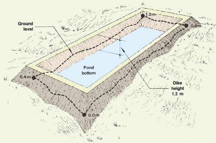 |
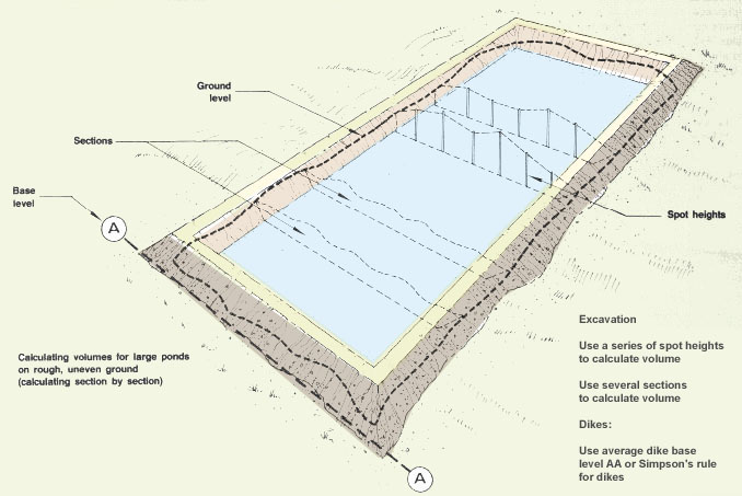
- for larger ponds more accurate results are obtained by calculating volumes section by section.
|
Excavation |
20. Alternatively, Method 2 using average ground level values can be applied. This method is faster, but less accurate.
Cut-and-fill volumes for groups of ponds
21. Frequently, for larger sites, several ponds and their water supply and drainage canals have to be built at the same time, so that the earthwork balances out across the entire project. This is clearly more complex, and will often require the assistance of a qualified engineer. There are, however, a few ways to estimate your requirements and to help guide your decisions, as you will learn below.
22. Water supply and drainage canals are usually more or less fixed at a specified level necessary for them to function properly. The volumes of earth involved, either excavated, built up or a combination of cut-and-fill, can be calculated according to the size of the canals. Any deficit or surplus soil must be found or used in the rest of the project.
|
Several ponds built at the same time
|
23. The site area can be split up into main groups of ponds, depending on location, pond type or size, or method of operation. You can then decide:
- whether the cut-and-fill for each group will be balanced, often the case in horizontal or gently sloping ground; or
- whether a surplus is expected for a particular group (if it is on high ground level and should be lower), or a deficit needs to be made up (if it is on low ground and needs to be built up). This situation is typical in more steeply sloping ground.
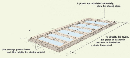
24. For balancing groups of ponds, you could arrange for all of the ponds to be at the same level. This solution is appropriate for horizontal or gently sloping ground. Calculate the cut-and-fill balance using Method 1. Use average ground and dike levels for the group of ponds as a whole with the perimeter and intermediate dikes. Add in the extra cut or fill required for the canals.
Note: if the intermediate dikes are small, disregard them altogether and treat the whole group of ponds as a single large pond.
|
Group of six ponds at the same level
|
25. Alternatively you can arrange for ponds to be at different levels. This solution is appropriate for more steeply sloping ground. Here each pond is calculated individually. A simple short cut is to calculate one pond at the top end of the site and another at the bottom. The intermediate ponds will then be set at intermediate levels between these.
|
Group of four ponds at different levels
|

26. Where a surplus or a deficit is involved, you should include it in the trial-and-error balance:
- if a surplus is required, add it to the dike volume quantity. The total figure is then used in the two-way graph;
- if a deficit is to be made up, add the required amount of soil to be brought into the area to the excavation volume. This total figure is then used in the two-way graph.
27. In several areas certain groups of ponds may have preset levels defined, for example, by water supply or drainage. In this case, cut-and-fill calculations will define the surplus soil produced or the deficit needed to be made up from elsewhere.
28. Another useful method is to draw one or more cross-sections through the site or through groups of ponds. You can quite simply adjust levels graphically to obtain an approximate balance of cut-and-fill.
|
Approximate balance of cut-and-fill |

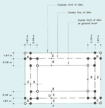
Staking out a cut-and-fill pond on horizontal ground
29. When the ground slope is less than 0.5 percent, the first steps of the method for staking out the centre lines of the dikes and the limits of the bases of the dikes are similar to the method described earlier for paddy ponds (see Section 6.7). The top of all the centre line stakes should be at the same level, indicating the dike's construction height.
30. In most cases, you will have made all the necessary calculations for staking out when calculating earth volumes.
| Example
If crest width of dike = 1.00 m;
and similarly for the other three dikes. |
 |
|
|
Plan for staking dikes
 |
Dike cross-section
 |
|
|
31. However, as the side slopes of the dikes have to be cut below ground level, you should stake out with short pegs one additional line defining the limits of the pond bottom. Note: the pond bottom area is the same regardless of the cut depth (see Section 6.4). |
Staking out pond bottom
 |
Staking out a cut-and-fill pond on regular sloping ground
33. When the ground slope is steeper than 0.5 percent, you have already learned that the parts of the dikes to be built above ground level do not have the same height on every corner of the pond. The top of the dikes needs to be level, but as the base of the dikes is on a variable level, the width of the dikes at the base varies from one pond corner to another.
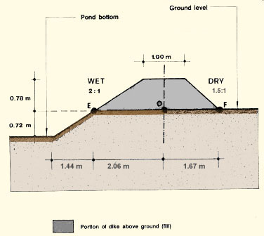
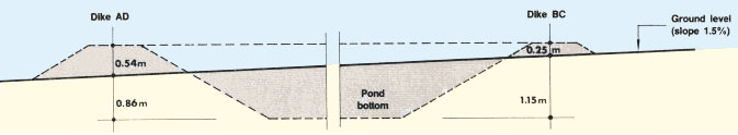
34. Once you have calculated how deep you need to dig at each pond corner to balance cut-and-fill volumes, the characteristics of the dikes are fully defined. In particular, their height above ground is determined for each pond corner, and therefore their corresponding base width is known. Now it remains to clearly mark these measurements on the ground before starting the construction. Proceed as shown in the example.
|
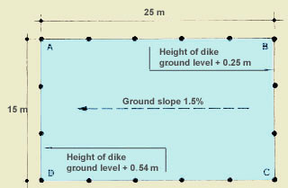
Example The pond to be built measures 25 x 15 m along centre lines. The dike is 1.40 m high with the following characteristics:
|
|
|
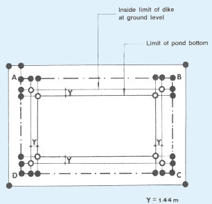
| (a) Stake out the four centre lines of the dikes AB, BC, CD and DA at 25 x 15 m, the width of the pond being parallel to the contour lines. |
Stake out centre lines ABCD
 |
(b) Calculate for each pond corner the width of the dike base
to be staked out on either side of its centre line as
X or Z= (crest width � 2) + (side slope x height above ground):
inside distance
X = (1 m � 2) + (2 x 0.54 m) = 1.58 m;
inside distance X
=(1 m � 2) + (2 x 0.25 m) = 1.00 m;
as corner B = 1.00 m;
as corner A = 1.58 m. |
Calculate width of dike base at each corner
|
|
|
(c) Stake out these distances X and Z on either side of the centre lines at each pond corner and in two perpendicular directions to obtain four new points at each corner.
(d) Join these new points to set out the four dike bases at ground level. Notice that the limits of the side walls are not parallel, owing to the difference in elevation along the pond length.
(e) The pond bottom is set out in the same way as previously described.
Note: it the ground slopes in more than one direction, as when the pond is set at an angle across the slope, the same method can be used. But in this case, each of the pond corners is at a different height and therefore none of the pond walls are parallel.
|
Example of dike base on ground sloping
in only one direction 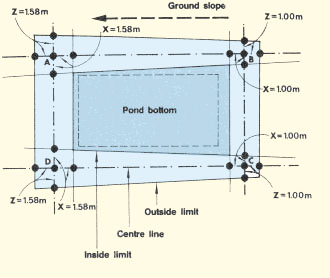 |
Example of dike base on ground sloping
in more than one direction 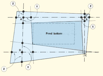 |
Staking out a cut-and-fill pond on a very irregular slope
35. If the ground slope is very irregular, it is best to proceed slightly differently.
(a) Stake out the centre lines with a series of pegs.
(b) On each of the pegs mark the height to be reached by the dike crest.
This forms a horizontal line.
(c) Calculate the required dike base width at each peg according to
the dike to be built there above ground level.
(d) Stake out the dikes' bases all around the pond, on short perpendiculars
set on the centre lines.
(e) Stake out and mark with lines the limits of the pond bottom after
calculating distances Y from the centre line as:
|
Y = (crest width � 2) + [(total dike height) x (wet side slope)] |
|
Example of dike base on very irregular
ground |
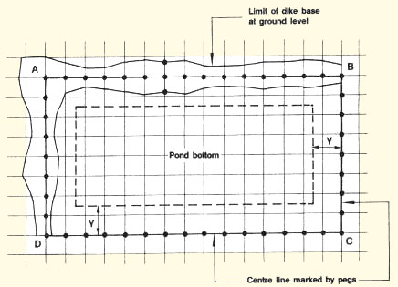
Building the dikes manually
36. Start digging within the area staked out as the pond bottom, cutting vertically along the edges of this area.
37. Throw this earth into the area staked out as the dike base. Spread it over the entire area into a layer about 0.20 m thick, wet it if necessary, and compact it well (see Section 6.2).
38. Build up and shape the dikes to ground level as described for paddy ponds (see Section 6.7), checking the pond bottom level from time to time.
39. Finish the dikes by cutting the earth left between the lines of stakes marking the inside limits of the base of the dikes at ground level and at pond bottom level. This also completes the wet side slopes.
40. Remove all stakes and lines, put back the surface soil on the dikes
and plant or seed grass (see Section 6.9).
|
|
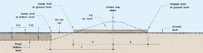
|
|
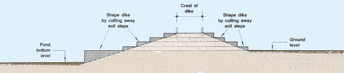
Completing the cut-and-fill pond
41. Clean the pond bottom.
| 42. In small ponds, give the bottom a gentle slope (0.5 to 1 percent) from water inlet to water outlet. |
Pond with sloping bottom
(slope 0.5 - 1 %)  |
|
|
43. In large ponds, either give the bottom a very gentle slope (0.2 percent) or, preferably, dig a network of shallow drains with a slope of 0.2 percent over the entire bottom area (see Section 6.10). Pond with a network of shallow bottom drains
|
 |
Building the dikes using machinery
44. When using machinery to build the dikes of a cut-and-fill pond, it is most important to check on the digging progress closely and regularly, to avoid cutting the pond too deep. Usually the bulldozer transports the soil by pushing, spreading it into a thin layer over the dikes' area and compacting it. Compaction in particular should be thorough, after wetting if necessary.
| Note: when machinery is being used, it
is also useful to set up a number of reference markers outside
the pond itself, as internal markers can easily be knocked
over. These reference markers can be used to recheck positions.
|
External reference markers for use with
machinery |
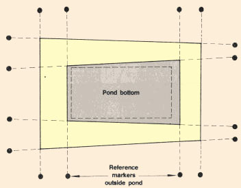
6.9 Protecting dikes against erosion by rain
Protect new dikes as soon as they are built
1. Newly built dikes should be protected against erosion by planting or seeding a grass cover on the crest of the dikes, on their dry side and on their wet side down to the normal water level of the pond.
2. To form a grass cover with the minimum of delay, proceed as follows:
(a) Spread a 10- to 15-cm layer of topsoil over the area to be planted. This topsoil is either brought back to the pond area from which it was earlier removed or is obtained from a nearby source.
(b) If possible, mix in some compound chemical fertilizer, for example a 13-13-13 mixture (NPK)1, at the rate of 50 to 100 g per m2 surface area or 400-800 g per m3 of topsoil.
1N = nitrogen; P = phosphorus; K = potassium
(c) Plant either cuttings or pieces of turf of the selected grass, see Table 30, at relatively short intervals.
(d) Water well immediately after planting and afterwards at regular intervals.
(e) After the sod is formed, cut it short regularly to encourage it to spread all over the area. If possible, apply about 0.1 g of actual nitrogen per m2 to accelerate the spreading.
3. For further advice, contact agricultural extension workers.
|
Preparing dikes for planting or seeding
grass
|
||
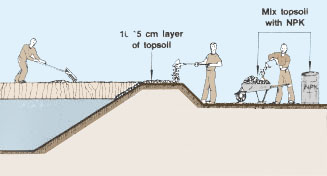 |
 |
|
4. If the weather is dry, you should plan for regular watering of the newly planted grass. Use mulching* to reduce soil evaporation.
5. When it rains heavily, use temporary protection, such as hay or other suitable materials, to avoid severe erosion of the dikes until a grass cover is formed.
6. Never plant large trees on or near dikes because their roots would weaken the dikes. In some areas, vegetable crops and forage bushes can be grown, but care should be taken to select plants with a good ground cover and with roots that do not weaken the dike by penetrating too deeply or disturbing the soil.
7. Care should be taken to keep the dikes in good condition, and only small animals should be allowed to graze or browse on them.
|
Never plant large trees on or near dikes
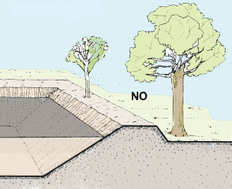 |
Crops may be planted on top of dikes
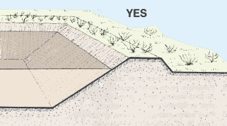 |
|
|
Only small animals should graze on dikes
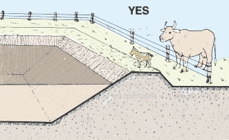 |
Selecting the grass cover
8. The best protection is obtained from perennial grasses (Gramineae) with the following characteristics:
- fast spread into a dense cover, through creeping, rooting stems (stolons*) or underground rhizomes*;
- well adapted to local climate, particularly if seasonally dry;
- easy to propagate vegetatively, for example by transplanting stolons* or rhizomes*.
|
|

|
|

9. Selected grasses recommended for the formation of a perennial grass cover on pond dikes are listed in Table 30.

|
|
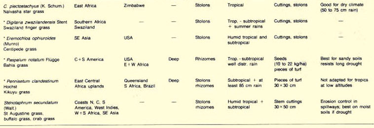
6.10 Pond-bottom drains
1. Pond-bottom drains are ditches that are dug on the bottom of the pond to help the water flow out and to direct the fish toward the pond outlet when harvesting.
2. You do not always need bottom drains for your pond, for example in small ponds with a sloping bottom. However, it is better to build bottom drains:
- when the bottom slope is insufficient;
- in large ponds more than 75 m long;
- in barrage ponds with an uneven bottom relief.
Designing the network of drains
3. Bottom drains can be designed in different patterns according to the pond bottom topography and shape.
4. If the bottom topography is fairly even, it is better to build a regular network of drains, for example:
- either radiating from the outlet if the pond shape is squarish;
- or in a fish-bone pattern if the pond is more elongated.
|
|
|
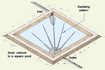
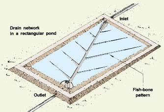
5. If the bottom topography is very uneven, it becomes necessary to build an irregular network of drains, connecting the various depressions and ensuring their complete drainage for harvesting.
|
Draining depressions in a barrage pond |
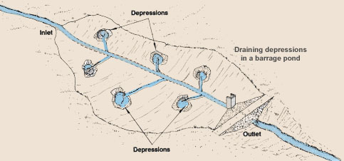
6. In certain barrage ponds where the upper shallow areas are swampy, it is better to dig a 2- to 3-m wide sloping drain along their perimeter. A central drain may also be added to increase the water volume available to fish.
|
Draining swampy areas in a barrage pond |

7. In paddy ponds, if soil is cut around the inside edge of the pond to form dikes, the trenches created should be linked in with the outlet drain.
|
Draining from excavation trenches in a
paddy pond |
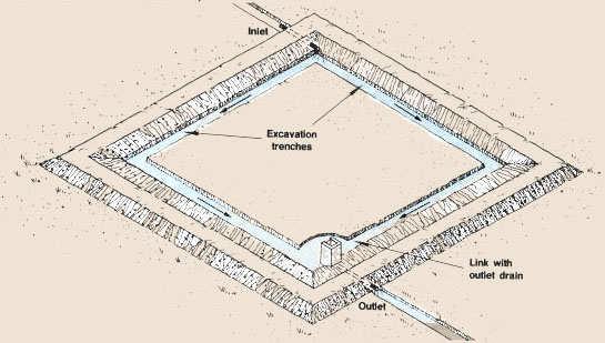
8. Bottom drains are usually designed as trapezoidal canals with the following characteristics:
|
Example of a trapezoidal bottom drain
|
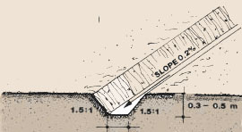
9. The distance between drains should vary from 4 to 8 m in small ponds, to 30 to 50 m in very large ponds. The number of drains should be kept to the minimum required to completely drain the water, as they will have to be regularly cleaned by hand.
| 10. The bottom drains should all communicate with
a harvesting sump dug in the deepest
part of the pond, usually in front of the outlet, where all.
the fish can be concentrated for their harvest (see Management,
section 11.2) harvesting sump dug in the deepest
part of the pond, usually in front of the outlet, where all.
the fish can be concentrated for their harvest (see Management,
section 11.2).
Note: a difference in elevation should be provided:
|
Bottom drain network with harvesting sump
|
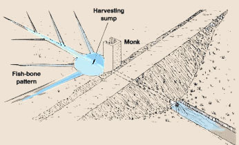
|
|
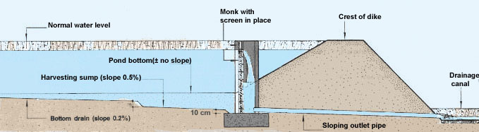
6.11 First filling of the pond
1. As soon as possible and before the completion of the pond, it is advisable to put it under water:
- to check that all structures function properly such as the water intake, the canals, the pond inlet and outlet;
- to check that the new dikes are strong and impervious enough;
- to accelerate the stabilization of these dikes.
2. For maximum security and efficiency, proceed in the following way.
(a) Fill the pond with water very slowly and up to a maximum depth of 0.40 m at the outlet.
(b) Close the water supply and keep water in the pond for a few days. During this period, check the dikes carefully. Repair crevices and collapsed sections, compacting well.
(c) Drain the water completely and leave the pond dry for a few days. Keep checking the dikes and repair them as necessary.
(d) Fill the pond again very slowly and up to a maximum level about 0.40 m higher than the previous time.
(e) Close the water supply. Check the dikes and repair them as necessary. After a few days, drain the pond completely.
(f) Repeat this process of filling/drying until the water level in the pond reaches the designed maximum level.
(g) Check and repair the dikes as necessary.
3. If there is a limited water supply, it will not be possible to follow the above procedure. In such a case, fill the pond very slowly and gradually, closing the water supply at regular intervals and checking on the dikes carefully.