1. Water intake structures depend on the type of pond you have. You learned earlier that a fish pond can be supplied with water from different sources (see Chapter 1). Several types of pond were defined by their intake structures:
|
|
|
|
|
|
|
Note: if the water supply is provided from a reservoir, the intake structures are usually part of the system that releases the impounded water into the pond feeder canal. They may consist of:
 |
 |
|
 |
2. The main elements of a water intake are:
3. There are many designs for water intake structures, some of which can be quite complex and require specialized design and construction. This manual concentrates on relatively simple designs that you can build by yourself or with the assistance of a good mason.
4. Main water intakes are used for the overall regulation and diversion of water supplies to a pond or group of ponds. In many cases, they are distinct from water transport structures, which are discussed in Chapter 8, and from smaller pond inlet structures, discussed in Chapter 9, which supply and control water flow into individual ponds.
5. The main purpose of an intake is to ensure a constant water supply that can be adjusted to suit local conditions.
 |
Section AA
 |
6. The pond site and its water feeder canal usually determine the location of the main water intake. If the pond is to be built along a stream, it is better to select a site that has:
|
Never place a water intake on the inside of the
curve
of a stream where silt, sand or gravel can build up  |
Choose a place on the outside of the curve where
the water flows faster and where silt, sand or gravel is less likely to build up  |
Note: avoid large rivers with a fluctuating water level. Be very careful to make sure the intake is not set above the minimum water level of the river.
1. There are two main types of intake:
| an open or free-level intake, in which the water supply levels are uncontrolled, and the intake operates in all water flow conditions. This system is simple and relatively cheap, but usually requires a reliable water supply that does not fluctuate excessively; |
 |
|
|
 |
2. In both cases, the important points to consider are:
 |
3. In the case of an open intake system, you must make sure that the level of the water in the supply source is sufficient at all times to allow you to take the water to the depth you need. You must also make sure that there is no risk of flooding the intake. As will be shown later, you can use an intake gate to control the incoming water supply.
4. In the case of a controlled level system, you can define the water level by setting the level of the diversion structure. The following points are very important.
(a) Check the longitudinal and cross-section profiles of the valley upstream of the structure to calculate the size of the flooded area that would be created behind the proposed structure (see Chapter 8, Topography).
(b) Aim to set the diversion structure at the approximately minimum water level required for water flowing in the supply channel.
(c) Make sure that flood water can be removed, either over a weir or through a side channel (see Chapter 11). If the structure is made of soft, easily erodible materials (earth or clay), it is better to use a side channel.
Note: if the control structure has to be set lower to reduce the size of the upstream pool, you may have to widen the supply channel to obtain the required flow (see Section 8.2).
|
Make sure that flood levels do not overtop
the control structure  |
If the control structure has to be set lower to
reduce the size of the upstream pool you may have to widen the supply canal to obtain the required flow  |
5. The methods needed to determine the relative levels are described in Topography for freshwater fish culture, FAO Training Series. Where possible, make use of local information. Ideally you should set up flow gauges and water-level stations. (See for example, Section 3.6 in Water 4).
1. The wider the water intake area, the less will be the head loss* as the water flows to the ponds. This factor may become important when there is very little head available.
2. In most cases, however, the water intake is about the same width as the supply canal connected to it. The size of the supply canal is chosen according to the flow required (see Section 8.2). If the supply canal is particularly wide, or if you want to increase the head loss at the water intake (for example, when the external water level is much greater than the level required within the supply canal), the intake can be made narrower than the supply canal. Generally, a narrow intake is easier to control, as the sluice boards or gate controls are easier to move.
3. As an approximate guide, Graph 6 gives typical flow rates through intake structures at different head loss. This head loss should be added to the supply canal head loss (Section 8.2) to define the relative levels of the intake and the ponds.
|
Example If 0.20 m is available between the minimum intake water level and the pond supply, a flow of 0.25 m3/s is required. It is calculated that head loss in the supply canal due to its bottom slope (see Section 8.2, paragraph 8) is 0.15 m. Possible head loss through intake is therefore limited to 0.20 - 0.15 m = 0.05 m or 5 cm. To ensure the required flow rate, the intake width would have to be at least 0.40 m or 40 cm (Graph 6). |
4. The intake control structures are described later (see Sections 7.6 and 7.7). First, you will learn about the diversion structures that are used for intakes (Table 31).
1, Simple diversion structures can be constructed from a range of materials. These materials are suitable for holding back water, but should not be used where water regularly overflows.
2. You can totally block the channel of a small stream with an earthen dam. Proceed in the following way:
(a) Design the dam to be built as if it were for a barrage pond (see Section 6.1).
(b) Divert the stream around the construction site. It is easiest to do this when the stream flow is low, for example, toward the end of the dry season.
(c) Stake out the dam base, set out the earthwork and build the dam across the stream channel (see Section 6.6).
(d) Construct the intake structure, the water feeder canal and its overflow away from the ponds.
(e) Gradually remove the temporary diversion, letting the stream establish itself in its original channel and fill the feeder canal with water.
Note: if necessary, protect the wet side of the new dam with rocks or stones.
 |
 |
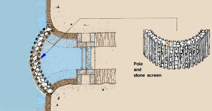
3. You can also block the channel of a small stream using a double row of wooden or bamboo poles lashed together with flexible lianas or vines, and packed with clay soil between the poles to prevent water seepage.
4. Remember that:
|
Double row of bamboo
 |
Bamboo or wooden pole barrier
 |
5. There are other ways you can build a barrier using planks and wooden poles. This kind of barrier can easily be removed in the rainy season when the water level begins to rise in the stream channel.
6. Two kinds of plank barriers are shown here. In the first, the planks are placed at a slight angle and braced by timbers. In the second, the planks are held in place between a light structure of logs and can be removed by lifting out one plank at a time.
(a) The planks should be well driven into the ground next to each other.
(b) The joints between the planks may, if necessary, be filled with heavy clay to make the barrier more impervious.
(c) You can also use medium- to heavy-weight polythene sheeting, overlapping bags, old inner-tubes or tarred felt or sacking to reduce seepage.
(d) The water level in the stream channel can be raised to reach a depth of 0.8 to 1 m.
 |
1. These structures can be used both for holding back water and for overflows.
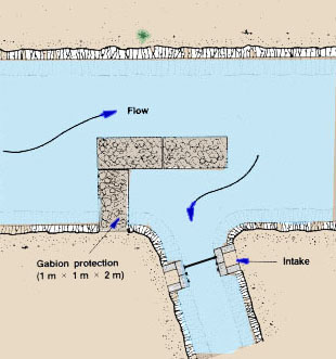
5. You learned how to construct gabions earlier (see Section 3.7). These baskets can be used very effectively in small streams with a maximum flow of less than 100 l/s to divert part of the water and to act as a spillway when floods occur. They are particularly suitable when gravel is found on the streambed and when the stones can be found locally.
6. Proceed as follows:
(a) When the water flow is minimum, divert the stream around the construction site.
(b) Stake out the base of the barrier you wish to build, for example, a rectangular area 3 m wide across the streambed, at a right angle to the flow direction.
(c) Across this area, prepare a horizontal platform at a depth of about 0.5 m below the streambed level.
(d) Build the foundation of the barrier on the horizontal platform, using one layer of thin gabions (2 m x 1 m x 0.5 m), as shown in Section 3.7.
(e) On top of this foundation build the body of the weir using two layers of thin gabions placed across and on the upstream part of the foundation. Anchor these baskets well into the stream banks and into each other.
(f) If necessary, protect the banks above the second layer with additional lateral layers of thin gabions. Fill in the gaps with compacted clayey soil.
|
Gabion barrier in a stream
 |
Diagram of a gabion barrier with additional bank
protection
 |
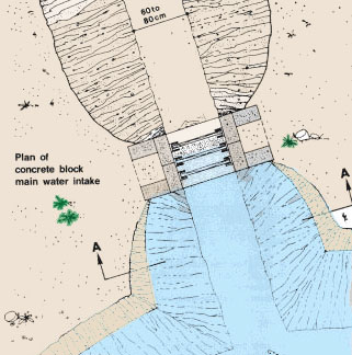
1. Adjustable diversion structures are more expensive and more complicated to build, but they provide an easier and more precise control of the water level in the stream channel. They are permanent structures made of reinforced concrete and removable planks. In the next paragraphs, you will learn about two simple designs for adjustable diversion structures. They can be changed to suit local conditions.
2. You can build a narrow adjustable barrage 2.5 to 3 m long and 1 to 1.5 m high, using reinforced concrete and strong planks 5 cm thick.
3. For a barrage made of 1 m planks and consisting of two columns 1 m high, you will need the following materials:
for verticals: (14 x 1. 10 m) x 2 =30.8 m
for cross-ties: (4 x 1.90 m) x 2 =15.2 m
(4 x 1.35 m) x 2 =10.8 m
steel bars 6 mm diameter, 14 x 0.60 m = 8.4 m.
Alternatively, reinforcement mesh, such as 10 cm square, 6 mm thickness can be used.
|
Plan of two-pillar barrage
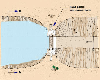 |
Section AA
 |
|
Building a two-pillar barrage
 |
Three-pillar barrage |
||
|
4. You can build a wider adjustable diversion structure barrage 4 to 7 m long and 1 to 1.5 m high using two lateral concrete pillars and one or more central ones, connected by two series of strong planks 5 cm thick. 5. For a barrage 1 m high made out of 1-m-long planks and with one central pillar, you will need the following materials:
for cross-ties:
plus far end pillars: 15.2 + 10.8 m = 26.0 m
|
 |
|
 |
|
Plan of three-pillar barrage
 |
Section AA
 |
6. Bury the foundations of the barrage in the dry streambed, anchoring them as far as possible into solid footing. The top level of the foundation should be about 5 cm below the level of the streambed.
7. Build each pillar into the banks of the stream. If necessary, build lateral wings from stones or concrete. You may use additional planks and fill the space between them with well-compacted clay soil. To avoid erosion, reinforce the stream bank next to each pillar with stones.
8. To make the concrete forms and fix the reinforcement well, you may need the assistance of a good mason.
Note: if you are unsure about the stability of the streambed, it may be safer to join the foundations to form a single foundation spanning the stream. This will require more material but will retain a fixed shape if the bed should erode.
Note: see how to control water flow and how to ensure good water control in section 7.6.
 Note: to make the concrete forms and fix the reinforcement well, you may need the help of a good mason |
|
Placement of steel bar reinforcement for three-pillar
barrage*
 * see two pillar barrage for plan section of end pillar |
1. The previous sections described how to define the level and size of major water intake structures. We now consider the types of structures to be used. There are two basic types:
2. You can chiefly control water flow in two ways:
| 3. Both of these systems are set in a holding structure,
which can be built of wood, bricks or blocks, concrete or steel like the
adjustable diversion structures described in Section 7.5. The structures
are built with one or more sets of anchoring slots or grooves in each
side of the control structure, as illustrated. Note: an intake can also be made with a swinging arm or flexible stand-pipe (see Section 10.3). This alternative is less common as a main intake, but can be convenient for controlling smaller water flows. Typical capacities of such pipes are given in Table 13 in Section 3.8. |
 |
|
|
Sluice boards set in wooden grooves
 |
Sluice boards set in cast grooves
 |
|
Adjustable penstock set in metal angles
 |
Sliding metal door set in cast grooves
 |
4. While penstocks are usually designed to seal tightly in a range of conditions, sluice boards are difficult to seal properly, especially for wider gates, where boards are more likely to twist and warp. One useful improvement is to use sealing flaps of heavy polythene sheet or old inner tube. Usually, however, three parallel sets of grooves are used, two for slipping one screen and one series of boards in or out and one for adding a second series of boards when the need arises to stop the water flow completely within the feeder canal.
|
Fold and nail sealing material
 |
 |
 |
||
|
Building a main water intake with sluice boards (dimensions suitable for a medium size pond system) |
||||
 |
|
Building a main water intake
 |
 Placement of steel bars for reinforced concrete
|
5. The flow rate through these structures when open can be estimated using Graph 6. For overflow intakes with boards, the control acts like a small weir (see Section 3.6, Water, 4) where water flow depends on the width of the board and the depth of the water flowing over it. Table 32 shows typical values. For underflow intakes such as penstocks, the flow depends on the difference in head from one side of the sluice to the other, and on the size of the opening. Table 33 shows typical values.
6. Care must be taken in all cases to minimize erosion, as the speed of flowing water may substantially increase around the gates. As a general rule, unless special designs are used (consult a hydraulics specialist), you should limit the drop across the intake to 80 cm.
1. Where conditions are likely to be turbulent, the sides and the outflow end of the structure may be reinforced using wood, light reinforced concrete, brick or boulders set in cement.
2. Intake structures can be protected from debris such as leaves or branches and from erosion by flowing water in several ways. Screens or guards can be used against debris in most cases, while gabions, wooden or bamboo piling, or rock reinforcement can be used for protection against erosion.
3. Screens can be set up in a number of ways, the most common being a simple side screen. They can also be set up horizontally, as inclined screens or even in the base of the supply stream.
4. In many cases, a single screen is used, usually made from steel bars 6 to 8 mm in diameter spaced 20 to 35 mm apart. This screen is sufficient for clearing larger objects. If smaller particles need to be removed, an additional screen of finer bar (e.g. 4 to 6 mm diameter) at closer spacing (5 to 10 mm), or steel mesh, can be used. The additional screen may be set up inside the main screen or may be incorporated into the intake structure itself.
5. For simple structures, the screen has about the same cross-sectional area as the main intake. To improve flow and to ensure the screen will operate even when partly blocked, it is frequently made larger than the intake (e.g. by using inclined "V" screens or horizontal screens - see manual, Management 21, Section 2.9).
6. Remember that if the screen starts to become blocked, it may direct water to diversion canals and so reduce the flow to the pond supply.
7. Screens can be cleaned by lifting the screen from its slots and brushing it, or by raising the hinged portion of a horizontal or inclined screen, or by arranging the screen so the passing water current will keep it clean. Mechanized automatic screens are also available, but these specialized installations are outside the scope of this manual.
8. You can learn more about screens in the next manual Management, 21.
 |
 |
 |
9. Intake structures can be protected in several ways and the principles of construction are given elsewhere in the manual.
10. A light framework of tied bamboo, woven netting, or posts and boards can be used for wall protection. Make sure the framework is well anchored, and do not let the water work its way behind the structure. If it does, erosion can be rapid, and the structure will weaken and lose its effectiveness.
11. Posts, tied planks or pickets can be embedded into the stream or along the sides. If well placed, they reduce erosion. If placed across an intake area, they can also act as a coarse screen, protecting the area from large and heavy debris.
|
12. Gabions can be used around the intake and to deflect water, if for example it flows strongly against a stream bank.
|
13. If large stones or rocks are available, they can also be used. Generally, the larger the stones, the better protection they provide. |
![]()