SCSP-SFDC/77/AEn/CP33
by
S. K. Teng, T.E. Chua and H. C. Lai
School of Biological Sciences
Universiti Sains Malaysia
Penang, Malaysia
1. GENERAL
The history of culturing marine fish in floating net-cages in Malaysia is fairly recent. A pilot project was established near fishing villages at Jelutong on the eastern coast of Penang Island. In order to introduce this method of fish culture to the fishing community, a family-unit experimental cage was also set up at Gertak Sanggol on the South-eastern end of Penang Island. This project was started in mid-1974 under joint funding from the International Foundation of Sciences (IFS), Sweden and Universiti Sains Malaysia as well as in close cooperation with a private Penang fish culturist. The main species of fish studied under culture conditions has been the estuary grouper, Epinephelus tauvina (Forskal). However, other marine fishes such as sea bass, Lates calcarifer; rabbitfish, Siganus canaliculatus, and S. javus; and threadfin, Eleutherenema tetradactylum are also experimentally cultured. Similar projects will be set up near the Muka Head Marine Biological Station of the Universiti Sains Malaysia if the site is found suitable.
With the diminishing landing of marine fishes in Malaysia, the urgency of culturing fishes of commercial importance hardly needs further emphasis. Over the last four years, this method of fish culture has been proven to be technically feasible and commercially viable.
This paper sums up the various aspects of cage design, construction, management and cost-benefit of floating cage culture of the estuary grouper, E. tauvina (Forskal) in Penang, Malaysia.
2. STRUCTURAL DESIGN AND CONSTRUCTION OF THE FLOATING NET-CAGE
The net-cages used for culturing the marine fishes are contained in a floating wooden platform of about 8.5 m × 5.5 m, surface areas. The wooden platform is made of the locally available Chengai Pasir wood, Hopea odorata which is reputed for its resistance to salt water and woodborers. Sealed polyethylene containers are used as floats to support the wooden platform. Detailed specification of a standard wooden platform with eight net-cages is shown in Fig. 1. The vertical wooden poles at the four corners and along the sides of the wooden platform serve as stabilizers while the cage is floating on the water as well as supporters when the cage is towed to shallow water for repairs and other maintenance work. The wooden platform is secured at four corners with ropes and wooden pegs driven into the seabed (Fig. 2).
Metal hooks sleeved with plastic tubing are used to hang the netcages to the wooden platform. The net-cages are made of 9 ply to 24 ply polyethylene netting with mesh varying from 1.27 cm to 3.18 cm. The sides of each net-cage are reinforced with polyethylene ropes. Cement blocks or bricks are used as weights to stretch the net-cages. Net-cages of size ranging from 0.81 m × 0.91 m × 1.07 m to 1.22 m × 1.52 m are used for nursing the young fish because of their convenience for handling especially in the event of disease treatment and growth monitoring. Netcages with size of 1.83 m × 2.13 m × 1.52 m are used for growing the fish to marketable size, while those with a size of 3.96 m × 4.57 m × 1.52 m are used for keeping the spawners as well as for other marine fishes such as snappers and threadfins that require more space for active swimming.
The wooden platform so designed is feasible for both experimental as well as commercial purposes. The current cost of a floating wooden platform with eight net-cages of 1.83 m × 2.13 m × 1.52 m each is estimated to be around M$2 000.001 (Table 1). With proper maintenance and upkeeping its life span is estimated to be about 3.4 years when placed in a semi-protected lagoon or bay.
Table 1. Cost breakdown for a unit of floating platform (8.5 m × 5.5 m) with eight net-cages (1.8 m × 2.1 m × 1.5 m each)
| Woods of Chengai Pasir | M$ 350.00 |
| Hardware | 160.00 |
| Nylon netting, ropes and nets | 1 000.00 |
| Empty plastic cans, 48 × M$5 | 240.00 |
| Labour charges | 250.00 |
| Total | M$ 2 000.00 |
3. CHOICE OF CULTURE SITES
Even though the use of floating net-cages has greatly minimized the danger of predation, the problems of environmental stress remains until a proper site is chosen in respect of pollution, tidal range, water current, accessibility by roads and sea from retail centres and seed collection areas. The preliminary observation confirms that the fish mortality rate in a highly organic rich area like the Jelutong site is several folds that at a relatively clean site like Gertak Sanggol. The Jelutong site is situated close to the sewage discharge outlet from the City of Georgetown. It is also true for the incidence rate of disease at the present site. However, at the proximity to the retail centres in the town and the seed collection sites at the Middle Bank in the Straits of Penang may override such a shortcoming. The cost of transportation is also greatly reduced. The tidal range at the culture site is 1.2 m and the current flow is recorded at a range of 0.50 – 0.62 m/sec which are strong enough to provide sufficient exchange of oxygenated water and mild enough to avoid unnecessary loss of energy as a result of active swimming by the cultured fish species. Some of the important physical and chemical parameters at the Jelutong culture site are shown in Table 2.
Table 2. Environment of the Jelutong culture site
| Water temperature | 26.5° – | 32.0°C |
| Dissolved oxygen content | 3.99 – | 9.33 mg/1 |
| B.O.D. | 0.51 – | 2.55 mg/1 |
| Salinity | 27.43 – | 32.10 ppt. |
| pH | 7.8 – | 8.7 |
| Current velocity | 0.05 – | 0.62 m/sec |
| Phosphate (po4) | 0.00 – | 1.00 ug/l |
| Chlorophyll-a content | 3 – | 8 mg/m3 |
4. REARING OF THE FISH
4.1 Seed collection and supply
Like many other marine fishes, e.g. yellowtail (Fujiya, 1976) successfully cultured in commercial scale, the grouper seed has to depend on the collection from natural waters. Although the induced spawning of this species is recently reported to be realized, produced seeds are not yet available.
The seed of estuary grouper and other marine fishes cultured in our present project are collected by the beach seine fishermen in the Middle Bank at a short distance from the culture site. The main grouper fry catching season occurs in a period from September to January the following year (Chua and Teng, 1977). The young fish are transported by keeping in the lower compartment of the rowing boat. Two small holes are perforated on each side of the compartment to facilitate an exchange of water in and out of the compartment when the boat is moving. A small triangular shaped floating net-cage made of fine nylon netting and pieces of wood is also used by the fishermen for transporting the fish from the fishing ground to the culture site.
4.2 Stocking and rearing of young fish
The newly-arrived young fish are first graded according to their sizes. Damaged fish are sorted out and dipped in weak sodium sulfamethazone for 20 minutes to prevent bacterial infection. The fish are then transferred to the floating net-cages with size ranging from 0.81 m × 0.91 m × 1.07 m to 1.22 m × 1.22 m × 1.52 m and stocked according to their size.
In the first few weeks, the young fish are fed with either the minced trash fish or young shrimp. The food is later gradually replaced by a moist pellet food prepared daily. The moist pellet food consists mainly of trash fish, fish meal, chicken feed, vitamins and minerals with wheat flour as the binder. The fish are fed to satiation in each feeding at a frequency ot twice daily.
When the fish reach the size of about 15–20 cm in total length they are transferred to larger cages for growing to marketable size.
4.3 Stocking and rearing of fish to marketable size
Net-cages of 1.83 m × 2.13 m × 1.52 m dimensions and above are used for rearing the fish to marketable size. Stocking density for grouper at size of 18–21 cm in total length or 82–130 g in weight is found to be around 30 to 60 fish/m3. When old and disused tires are provided as hiding space for the fish in the cage, this stocking density could be further increased without any adverse effect on their growth.
The optimum feeding frequency for the growing grouper is to feed the fish once in two days. Fish are fed to satiation in each feeding. Increased the feeding frequency to 3 times daily does not enhance the growth significantly. The total food intake per feeding is the highest when the fish is fed once in two days. The intake of food is found to be related to the amount of food remaining in the stomach, attaining maximum intake when the stomach is empty. The food deprivation time in growing grouper was found to be about 36 hours after which over 95% of the food in the stomach was evacuated. Hence feeding the fish at 48 hours interval, greatly enhanced maximum intake and efficient utilization of the food. However, in young grouper the food deprivation time is about 16–17 hours, a lot shorter than that of the growing grouper. This is why the recommended feeding frequency for young grouper is two times daily.
Either trash fish or self-prepared moist pellet food are used to feed the fish. The food conversion of fish fed with moist pellet improves considerably over the fish fed with chopped fish. Feeding on moist pellet is found to be enhanced by about 11% over those feeding on chopped trash fish. Thus this greatly compensates for the higher cost of preparing the moist pellet food.
Fish with size of 82–130 g or 18–21 cm in total length stocked at density of 30 to 60 fish/m3 grow to a marketable weight of about half a kilogram within a period of 6 to 7 months. In order to reduce the size hierarchy within the cage and to ensure a uniform growth of the fish, constant grading of the fish is therefore necessary. It is especially true for the young grouper.
5. MAINTENANCE OF CAGES
Fouling has been one of the many problems facing marine aquaculture industry. Fouling by marine organisms such as barnacles (Balanus spp.), oysters (Pinctada vulgaris, Crassostrea sp.), tunicates (Molgula sp.) and compound tunicates, green algae (Enteromorpha sp.) on the net-cages will soon start once the net-cages are put into the water. Cheah (1974) reported that net-cages with meshes of 25 mm and 7 mm will be fouled in a period of 1 to 2 weeks.
Under tropical climate, the rate of fouling is much accelerated. Frequent changing of the net-cages will therefore ensure better growth due to the more efficient flow of water in and out of the cages resulting more adequate supply of oxygen. The sharp edges of the barnacles and oyster shells will injure the fish through abrasion during feeding. Our observations indicate that in water heavily fouled with barnacles and oysters, the incidence rate of bacterial disease in unchanged cages is about 2–3 times higher than those kept in net-cages with frequent changing.
Net-cages of smaller mesh (1.27 – 1.90 cm) are changed once every week, while those with 2.54 cm mesh once in two weeks. Net-cages of 3.18 cm mesh are changed once a month. The clearing operation involves the drying of the nets in the sun for 2–3 days, the dead barnacles and other fouling organisms are crushed and knocked off the net with a wooden club. With regular cleaning and proper maintenance, the nets can last at least 5 years. Observations show that the platform made of Chengai Pasir wood and polyethylene floats and nets can withstand tropical heat, woodborers and fouling and last longer than those made of other materials.
Neglect in checking the damaged meshes on the net-cages could easily incur loss of fish during culture. It is especially true for nets with bigger mesh. The cleaned net-cage should therefore be carefully checked and damaged meshes mended before it is put into the sea and stocked with fish.
6. DISEASE AND CONTROL
The most common fish disease at our culture site is the redboiled disease caused by a gram-negative bacterium, Vibrio sp. The symptom of the disease begins with the infection of the fin and lesions gradually spread to the lateral sides of the body and eventually reaches the ventral and the anal area (Fig. 3). The infected fish show sign of weekness initially and die in 3–5 days if no treatment is received during the early stage of infection. During the early phase of infection, the young fish can be effectively cured by vibramycin and sodium sulfamethazone baths. Intra-muscular injection of terramycin is recommended for growing groupers.
Fish under overcrowded conditions and improper feeding may be infested with monogenetic gill flukes. They can be removed by bathing the infested fish in freshwater for 45 minutes.
The ectoparasite such as isopods so commonly found in the mouth cavity and the gill chamber of the rabbitfish are rare in groupers. There seems to be no effective chemical means of getting rid of these ectoparasites but to remove them mechanically.
At the onset of the pilot project the mortality rate was found to be as high as 80% or more which accounts for the small profit margin experienced by a private fish farm. With the help of this on-going project, the mortality rate is reduced to about 20%. In the new culture site at Gertak Sanggol with much cleaner water, the mortality rate is further reduced to be less than 10%.
7. CAPITAL AND OPERATING COST
The total cost of the on-going project was M$27 140.00 when it was incepted in 1973. To launch a similar project now would incur a cost of $36 100.00 amounting to an inflation of about 33% over the past four years or about 8% yearly (Table 3).
To run a project consisting of eight units of floating cages with efficiency would require four labourers, whose wages accounts for about ¼ the total operating budget (Table 4). The next two large expensive items are the purchasing of seed and feed, each accounts for over 20% of the operating cost. As the site is on the beach, the equipment and facilities are under the constant scorching effect of tropical sun and corrosive sea water, we place the depreciation value about 18% of the total operating cost. The cost of production per fish is estimated to be M$2.3/kati1 or 37% (M$2.3/M$6.25). The operating ratios would reveal the degree of viability of such a venture. The net income constitute about 55% of the gross return, roughly 147% of the operating cost or 70% of the total capital investment plus operating cost. The high net income to operating cost ratio indicates the low cost required to run the day to day operation of the cages once the capital, slightly high, is invested. The capital investment can be substantially reduced with some improvisation such as the making use of bamboo substitute for wood and floats.
Table 3. Capital and operating ratio of a pilot project at Jelutong
| Capital cost* | |
| Net cages (8), 8.5 m × 5.5 m × 1.5 m × 8 | M$ 10 000.00 |
| Boat | 3 000.00 |
| Building | 12 000.00 |
| Freezer | 1 000.00 |
| Electric mincer | 600.00 |
| Tanks (5) M$60 × 5 | 300.00 |
| Air pumps (20) M$12 × 20 | 240.00 |
| M$ 27 140.00 | |
| Operating ratio | |
| Net income/gross return* | 54.69% |
| Net income/operating cost** | 146.87% |
| Net income/total capital + operating cost | 69.67% |
* Estimated at current value in Malaysian Ringgit
** Data from Table 4
Table 4. Cost benefit of pilot project
| Gross return from 14 000 fish* (17 500 katis or 10 587.5 kg)** at M$5.00 per kati | M$87 500.00 | % | |
| Seeds (20 000 × M$0.50)*** | 10 000.00 | 25.2 | |
| Feeds (M$0.17/kati) | 8 500.00 | 21.5 | |
| Disease control (M$0.10/fish) | 1 000.00 | 2.5 | |
| Labourers (4) (M$200 × 4 × 12) | 9 600.00 | 24.3 | |
| Fuel and electricity | 1 000.00 | 2.5 | |
| License fee (TOL) | 480.00 | 1.2 | |
| Miscellaneous expenses | 2 000.00 | 5.2 | |
Subtotal operating cost | M$32 580.00 | ||
| Depreciation per year | |||
Net-cages (25%) | 4 000.00 | 10.0 | |
Equipment (20%) | 620.00 | 1.6 | |
Boat (25%) | 1 250.00 | 3.2 | |
Building (10%) | 1 200.00 | 3.0 | |
Total cost | M$39 650.00 | 100.0 | |
Net profit | M$47 850.00 | ||
Cost of production | M$ | 2.30/kati or | |
| M$ | 3.80/kg | ||
* 8 units of cages
** 1 kati = 0.605 kg, 1 fish weighs 1.25 kati at harvesting
*** Calculated at 30% mortality
8. AN EXTRAPOLATION
With the above cost benefit analysis it is possible to predict the viability of setting up family floating fishpens of 4 units in the State land under TOL (Temporary Occupation License) lease. The initial capital outlay is estimated at M$7 000.00 (Table 5). If a total of 4 800 grouper fingerlings are cultured with a mortality rate of 20%, the net profit will be as high as 60% (i.e. M$12 065/M$20 000) of the gross return income per month will be as much as M$500.00 about 5 times the average monthly income of a fisherman in Peninsular Malaysia.
Table 5. Capital cost of a family floating fishpen
| Net-cages (4) 8.5 m × 5.5 m × 1.5 m × 4 | M$ 5 000.00 |
| Outboard motor boat | 1 000.00 |
| Small equipment | 1 000.00 |
| Total | M$ 7 000.00 |
Table 6. Cost benefit of a family fishpen for grouper culture
| Gross return from 4 000 fish (5,000 katis or 3.025 kg) at M$4.00 per kati | M$20 000.00 |
| Seeds (4 800 × M$0.50) | 2 400.00 |
| Feeds | 3 360.00 |
| Labourers (2 family members) | - |
| Fuel | 500.00 |
| License fee (TOL) | 50.00 |
| Miscellaneous expenses | 500.00 |
Subtotal operating cost | M$ 6 810.00 |
| Depreciation yearly | |
Net-cages (25%) | 625.00 |
Equipment (25%) | 250.00 |
Boat and engine (25%) | 250.00 |
Total cost | M$ 7 935.00 |
Net profit | M$12 065.00 |
Net income per person per month | M$ 503.00 |
9. CONCLUDING REMARKS
The history of floating cage culture of fish is fairly recent. It has its potential as well as limitation. With the participation of the under-employed fishermen in this country, it could bring substantive increase in their income during time of diminishing landing of fishes, by exploiting the lagoons and bays presently under-utilized. The viability of family floating fishpens will depend on the acquaintance with the latest techniques of cage construction, disease control, operation and management. In this regard, a demonstration farm has to be set up by the Government or semi-government agency to offer fishermen training opportunity. The problem of seed supply will not arise initially though in the long run the industry will depend on the provision of seeds through induced spawning and the availability of a seed bank like the milkfish example in the Philippines.
The result of our pilot project shows that the yield of fish per acre in cage culture increases by about 20 times that of the culture fisheries in ponds or enclosed lagoons.
The cage culture of marine fish also eliminates the frequent meteorological disruption during the monsoon seasons and avoid the normal seasonal fluctuation of catch. It is anticipated with sufficient number of cages, the fish can be harvested continuously throught the year. The floating cage culture can also eliminate the large mortality of fish as a result of pollution and epidemic diseases through the ease of treatment and handling of fish in cages.
The cage culture of fish also has its inherent limitation. The most obvious draw-back is fouling, liable to theft, inadequate supply of seed and apparently high cost of capital investment. The suitability of floating cage culture of fish in exposed environment remains to be investigated. The design of the present net-cages also suits only the relatively calm and protected estuaries. If the meteorological effects are minimal, the cost of construction can be substantially reduced by using improvised material like bamboo which serves as float as well as platform. The longevity of the cage and nets can be extended with greater care of maintenance and the operating cost trimmed by enticing family members to run the project.
10. REFERENCES
Brett, J.R., 1973 Marine fish aquaculture in Canada. The practice and the promise. Bull. Fish. Res. Bd. Can. (188): 53
Cheah, S.H., 1974 An ecological study of the marine fouling organisms associated with the floating cage-nets used for fish culture. Honours Thesis, School of Biological Sciences, Universiti Sains Malaysia, 100p.
Chen, F.Y., et al, 1977 Artificial spawning and larval rearing of the grouper, Epinephelus tauvina (Forskal) in Singapore. Singapore J. Pri. Ind. 5 (1): 1–21
Fujiya, M., 1976 Yellowtail (Seriola quinqueradiata) farming in Japan. J. Fish. Res. Bd Can. 33 (4): 911-5
Lai, H.C. and T.E. Chua, 1977 Limnological features of Muda and Pedu reservoirs with notes on their suitability for fish culture. Malay. Agric. J. (in press)
ACKNOWLEDGEMENT
The authors express their gratitude to the Swedish International Foundation of Sciences and Universiti Sains Malaysia for their financial assistance to the pilot project in culturing marine fishes at Jelutong; to the Southeast Asian Fisheries Development Center (SEAFDEC) and the FAO/UNDP South China Sea Programme (SCSP), for supporting the participation of one of the authors (LHC) to the Workshop; and to Y.B. Tan Sri Datuk Haji Hamdan bin Sheikh Tahir and Dr. Wong Tat Meng, for their permission to read this paper at the Workshop.

Figure 1. Floating net-cages suspended from a common platform
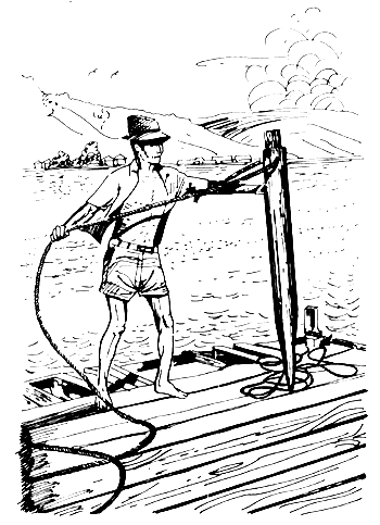
Figure 2. Wooden peg used to drive into sea bottom for anchoring floating fishpens

Figure 3. Grouper suffered from red boil disease
SCSP-SFDC/77/AEn/CP26
by
V.N. Alferez
SEAFDEC Aquaculture Department
Freshwater Aquaculture Station
Binangonan, Rizal
Philippines
1. INTRODUCTION
1.1 Development of lake fishpens
Fishpens and fish cages as methods of fish culture were introduced in the country for a number of years now. This type of fish culture was first tried by the Bureau of Fisheries and Aquatic Resources (BFAR) in the culture of common carp, tawes and goby or “biyang puti” in the lake shores of Cardona, Rizal, in 1965. In 1968, several uniform-sized wire mesh were set around Sampaloc and Palakpakin Lakes in San Pablo City in the culture of Tilapia (Felix, 1975). In 1970, an experimental fishpen for milkfish culture was constructed by the Laguna Lake Development Authority (LLDA) at Looc, Cardona, Rizal, covering an area of 38 hectares (Nicolas, et al, 1976).
In each of the above cases, the results were very encouraging particularly in the culture of milkfish and tilapia so that in 1971, a number of enterprising people invested in the fishpen culture of milkfish in Laguna Lake.
In general, fishpen and fish cages can be classified into two. The first one is the fixed type where the pen supporting structure is embedded into the bottom of the lake and the other is the floating type where the whole enclosure is floated on the surface of the water, but it is moored or anchored to the bottom by means of weights.
In Japan, fishpen culture is a well-developed industry. It started in Seto, Nakai and Yoshima Bay, Shikoku Inland seas in the culture of octopus and yellow tail. Other countries like Thailand used baskets in the culture of catfish. In Indonesia, carp culture in cages set in shallow rivers is also used. In Scotland, several years of work has been made on a range of different cage designs oriented towards salmonid culture. Work in Alaska in 1973 carried out by the National Marine Fisheries Service with coho salmon smelt rearing, and projects to rear coho and chinook salmon in Washington in 1975 used extensively large floating net pens.
It can be gathered from these reports that fishpen as a method in fish culture has gained favourable attention from several countries around the world. A number of these studies dealt extensively on the design and construction of these enclosures.
1.2 Brief description of Laguna lake
Laguna de Bay is the largest of the 70 lakes found in the Philippines. It has an area of about 91 000 hectares and an average depth of 2.8 metres (Nicolas, et al, 1976).
The lake is basically a freshwater lake but because of its low elevation from sea level, it comes in contact with salt water. Salinity varies from 0.141 ppt to 1.35 ppt (SEAFDEC Aquaculture Department, 1977). The deepest portion of the lake is located in the northern tip of Talim Island which lies in the Central Bay. The Pasig River which flows into Manila Bay is the only outlet. The lake is replenished by the number of rivers and springs, and by precipitation. During the rainy season, the lake water level rises to as much as 20 m. The ordinary low lake stage is an elevation of 10.5 m which coincides with the mean sea level in Manila Bay (Delmendo and Gedney, 1974).
Fig. 1 shows the lake, divided into four portions, as follows:
West Bay - the westernmost and biggest portion, starting from its outlet at the Napindan Channel and extending to the west shore of Talim Island, average depth of this bay at low water is about 3.5 m
Central Bay - starts from the vicinity of the southern tip of Talim Island and Jala-jala Peninsula and extends northward to Tanay and Baras. Average depth is about 4 m
South Bay - that portion immediately fronting Calamba, Los Baños and Victorias. Average depth is 4 m
East Bay - easternmost portion beginning from Victorias to Pangil and Siniloan. Average depth is 3 m
1.3 Extent used for pens and species stocked
Although the initial fishpen cultures proved successful, the industry started to develop only in 1972. A survey was made in 1973 showed that there were 993 operators in Laguna Lake with fishpens ranging from less than one hectare to more than 100 hectares and a total area of 4 802 hectares. Of this number, 200 (20%) have their fishpen constructed in the Central Bay and 773 (80%) are found in the Southern Bay (Delmendo and Gedney, 1976).
Majority of these fishpens are stocked with milkfish (Chanos chanos) In a survey conducted in 1976 of 200 samples, 96% raised pure milkfish, 1.75% raised milkfish in combination with other species, 1.71% raised Tilapia and only 0.58% raised other species (Nicolas, et al, 1976).
1.4 Estimated weight and value of annual production
The average annual production of milkfish in the lake is 4 tons per hectare as compared to fishpond which is only about 638 kilos per hectare. Delmendo and Gedney (1974) presented the following data obtained in 1973 as follows:
“Three important findings were revealed by the 1973 data:
First, the productivity of the fishpen areas averaged 4 000 kg/ha as compared to 245 kilos/ha in open water, equal to a factor of 16.
Second, the value of the harvest was
16 000/ha in open water, equal to a factor of 25, thus reflecting both higher productivity and higher value per kilo of fishpen production.
Third, the total yield of the 4 800 ha of lake fishpens was 19 200 000 kilos as compared to 20 700 000 kilos for the remaining 85 000 of open water or simply the 4 800 ha of fishpen produced about the equivalent of the 85 000 of open water.”
1.5 Potentials
The potentials of the fishpen industry in Laguna de Bay is tremendous in terms of the increased production and economic upliftment of the surrounding communities.
The present hectarage of fishpen can be easily doubled or tripled with the use of improved designs and method of construction with more emphasis on the engineering aspects of the fishpen structure.
It cannot be denied that typhoons and strong winds greatly affect the fishpen structure. Production is dependent not only on the food supply in the lake but also on the strength and durability of the enclosures.
It is this purpose that this paper seeks to achieve. It is an attempt to look into the basic engineering problems of existing fishpen and to present an improved design which could sustain the elements and other forces.
2. FISHPEN/FISH CAGE DESIGN
2.1 Design criteria
There are two basic criteria in the design of any structure. These are: the strength criterion in which a member or a structure resist a given force; and the rigidity or stiffness criterion in which the member sustains deformations due to the given force.
As applied to fishpen structures, these two criteria must be considered in the design of the composite structure, i.e. structure whose members react to the given load.
2.2 Observation on existing fishpen design
Before proceeding further, a review of Laguna de Bay's existing fishpen designs and construction is in order. It has been observed from ocular surveys around the lake that there are differences in designs and construction of fishpens. Basic of which is the framing arrangement in resisting the wind, wave and water hyacinth drift. Fig. 2 shows the types of framing arrangement. Type 1 as shown in the edge view consist of vertical pole and a bracing fastened at the top. This type has the advantage of resisting the forces acting against the bracing but it is weak in the other direction. It is less rigid in that direction because of possible uprooting during excessive loads.
Type II is an improvement of Type I in that there are now two bracings, one on each side of the pen. The disadvantages lie in the harvesting of the stocks when drag seines (pukot) are used. Also it would be difficult to prevent escaping of the stocks when topping of the net by water occurs. Type III is double enclosures. The outer one serves as “breakwater”. The enclosure prevents water hyacinth from destroying the inner enclosures. It is attached with a large mesh net. The inner enclosure serves the same purpose as in Type I and Type II.
There is one apparent defect in all the types described above and this is undoubtedly the small lateral rigidity along the vertical plane of the structure. Although the bracings are placed to take care of lateral forces such as wind, wave and water hyacinth drift, the horizontal struts provide minimal resistance to swaying when one or two bracings are destroyed or uprooted due to excessive forces.
3. LATERAL FORCES
In designing structures, no amount of structural analysis is satisfactory unless the forces which act on them are not properly determined. In the present case, there are three important forces which act on the fishpen. These are the effects of wind, waves and drifting water hyacinths.
3.1 Wind force
To determine the wind force which act on the fishpen, one has to determine the wind pressure and the surface areas which the wind acts. These are surface areas of poles and nettings, thus
F = Pn × A
| Where F | = | force acting on a member |
| Pn | = | pressure of wind normal to surface |
| PN | = | .002558V2 |
| V | = | velocity wind in mph |
| A | = | area on which the wind acts |
Table 1 shows basic wind pressures for different height zones above the ground (Carillo, 1975). Fig. 3 also shows the wind-pressure-map areas for the Philippines.
3.2 Wave action
Waves caused by wind are very complex. The water level change observed at a point in a body of water depicts patterns of irregular shapes. At present, actual wave observations still involve some amount of difficulty and sufficient observation data can rarely be obtained. Katoh (1975) suggested that estimate of the wave strength can be obtained from observation data from the wind. He presented a rigorous analysis of wave action on levees.
In fishpen structures in the lake, the wave action is small compared to levees on dikes. Wave pressure are limited to the size of the supporting members in the pen and the nets. The latter, in fact, contributes induced stresses on the pen by means of a “sail effect” which is more evident in wind forces. This involves the tagging of the nets away from the pen. Wave pressures are minimal because the waves hardly reach into breakers which can be devastating in the case of levees.
3.3 Water hyacinth drifts
No attempt has been made in the movement of water hyacinths and other vegetation in the lake and its destructive effects on the fishpen structures. This movement is mainly due to wind action on the surface of the mass of water hyacinths which has been observed to be as wide as 1–5 hectares in several occasions. The general direction of the movement is along the prevailing wind direction of the northeast and southwest monsoons. Imagine a hectare of water hyacinths which has been formed by wind action to a more compact mass with an approximate total weight of (a fully grown water hyacinth plant can weight as much as 10 kilos occupying an area of 0.10 sq.m) 1 000 tons moving towards a fishpen at the rate of, say ½ ft/sec and 1 sec on impact. This can induce a force on the fishpen equivalent to 15.0 tons.
3.4 Design of supporting structure
Two basic designs of supporting structure are presented in resisting the forces described in the preceding section. The fixed type of fishpen will be discussed because of its extensive use in the lake. A square composite structure of fishpen is used to facilitate discussion although a circular shape is more efficient.
There are two planes in the structure which require analysis, namely: plane parallel to the plan of the fishpen; and plane which is parallel to the sides. Fig. 4 shows the two planes in consideration.
3.4.1 Model one
Fig. 5 shows the forces assumed to act on the panel joints as in (a). As far as the horizontal plane is concerned, the forces are being resisted by the truss framework lying in that plane. In turn, this truss framework transmits the load to the vertical plane as in (b). A simplified framework where the truss system in (b) is assumed to act as a rigid member as shown in (c). Similar analysis can be made on the other direction.
Once the forces are determined, the members of the truss framework in Fig. 5(a) can be found by the methods of truss analysis. Similarly, the vertical poles in Fig. 5(c) can be found by considering the pole to be a cantilever. The fixed end can be approximated to be at 30 cm from the embedded end of the pole.
3.4.2 Model two
Design model two is almost similar to the first one. The difference lies in the framework members, the web members perpendicular to chords are missing in model two. Likewise, the diagonal in the vertical framework are farther apart than in model one. Basically, they resist the same forces and attain similar deformation. However, model two is much better in terms of the number of members involved which would result in a lesser cost of construction compared to model one.
In any case, the idea is to provide sufficient strength and rigidity when acted by these forces.
3.5 Site selection
Site selection as part of the pre-construction period is a very important aspect of the fishpen industry. Assuming that availability of fingerlings and market demands are not a problem, the following factors must be considered in the selection of the fishpen site as far as engineering is concerned:
The fishpen must be located, if possible, in an area where there is natural protection from strong and gusty winds. In Laguna Lake the existing fishpens are located in these areas. However, the protection is only partial because it is only on one side.
The depth must be not more than 2 metres during the lowest water level (Felix, 1975). In areas where the depth is more than 4 metres, it might not be possible to use fixed pens. In this case, floating pens may be used.
Avoid turbid or polluted water (Felix, 1975).
Muddy clay or clay-loam soils are best types of bottom soils. This is desirable for easy staking of the poles as well as better adhesive action between poles or mud.
4. METHODS OF CONSTRUCTION AND MATERIALS USED
The fishpen in the lake can be grouped into two according to the materials used for the enclosure. The first group are made of all bamboo poles for the supporting system and rubber tire strips as typing material. This group of fishpens are found mostly in the Southern Bay along the coast of Laguna Province. The other group found mostly in the Central Bay are made of combination of bamboo and wooden poles placed alternately between each other along the length of the pens. The poles are fastened by means of polyethelene ropes of 5–6 mm in diameter.
Various advantages and disadvantages are given in the use of all bamboo poles and combination poles. In the case of all bamboos, staking of the poles is not a difficult job and requires minimal labour cost as compared to the use of wooden poles which requires a good number of persons to stake one into the mud. The supply of bamboo poles is considered adequate compared to wooden poles. In addition, the cost of one bamboo pole is three to four times less than the cost of wooden poles. Wooden poles, however, are stronger and more durable compared to bamboo poles. Also, the fishpens under this group requires lesser bracing compared to the other group. The disadvantage of wooden poles is its buoyancy. Staking becomes extremely difficult at times, whereas bamboo poles are staked easily. This is done by removing first the central portion of the node thus reducing the buoyancy. In addition, once the bamboo poles are staked into the mud, the space inside the bamboo is filled with mud or clay or soils thus, making it difficult to uproot. Not only does staking of wooden pole prove difficult, but also it is uprooted by buoyancy when swaying occurs due to wind and wave action because of the loosening of the clay bottom immediately surrounding the embedded pole.
With regard to the tying materials, originally, G.I. wires 1/16 in diameter were used. As these were easily eaten up by rust, the use of polyropes were adopted. When the cost of polyrope increased, rubber tire strips were introduced. The cost of this tying material has increased lately. However, the cost of this material is still lower than the polyrope. Because of this, more and more operators have been using this kind for tying.
On the netting, there is a slight difference and this is on the mesh size. Some operators use double netting; a large mesh on the outer pen to protect the stocks from water hyacinth and other flotsam; and a finer mesh in the inner side to prevent the stock from escaping.
4.1 Methods of construction
Perspective details of fishpen construction are shown in Fig. 7. The outer line of pole is laid out by means of a string running along the length of the sides and tied to two poles to make it stationary. If necessary, additional intermediate poles may be placed to avoid touching the water due to sagging. As soon as this is done, the first set of poles is staked. After the 10th pole, horizontal struts are tied to the poles and the truss framework is worked on. Two teams may be employed; one team takes care of the staking (3–4 persons) and the other team takes care of the truss framework (also 3–4 persons).
The netting method as described by Delmendo and Gedney (1974) is as follows:
“The nets usually come in rolls about 1.4 m wide. The nets are sewn together, both in width and length, with a sewing machine using heavy duty nylon thread to make a continuous long horizontal fence screen which can be directly attached to the posts. The top and bottom edge of the assembled screen are also reinforced with nylon rope, as drawn in Fig. 11.
Two pieces of ¼-inch rope are used as reinforcement for the bottom of the screen, and another is used along the top edge.
One of the ¼-inch rope is unfolded along the edge of the screen panel at the top and one at the bottom. The second rope at the bottom is tied to the enfolded rope and used to secure concrete sinkers of about 1 kg to weight the net to the bottom. Additional anchorage is achieved by pegging the bottom ropes with bamboo stakes driven into the lake bed. The concrete sinkers consist of a tin can (milk or sardines) with concrete poured inside and a length of nylon rope incorporated with the concrete.”
The present system of anchoring the net is similar to the above description but it varies in the weights used to anchor the bottom edge of the nets. The present system employs a hand-made stone disc 5" in diameter and 1" thick of basalt material.
4.2 Costs of construction
Using the design models, the estimated cost for a one-hectare area is as follows:
| Material | Quantity | Model One | Quantity | Model Two | |
| 1. | Bamboo poles at  7.00 7.00 | 1 260 pcs | 8 840.00 | 800 pcs | 5 600.00 |
| 2. | Netting (nylon net) | 2 080 m | 15 000.00 | 2 080 m | 15 000.00 |
| 3. | Knitting twine (nylon) | 4 kg | 80.00 | 4 kg | 80.00 |
| 4. | Nylon chord | 15 rolls | 300.00 | 15 rolls | 150.00 |
| 5. | Tying rope #6 | 20 rolls | 500.00 | 15 rolls | 375.00 |
| 6. | Stone sinker | 135 pcs | 67.50 | 135 pcs. | 67.50 |
| 7. | Guardhouse | 1 | 3 000.00 | 1 | 3 000.00 |
 27 787.50 27 787.50 |  24 272.50 24 272.50 | ||||
| 8. | Labour (20%) | 5 553.50 | 4 854.50 | ||
| TOTAL |  33 341.00 33 341.00 |  29 127.00 29 127.00 |
5. CONCLUSIONS AND RECOMMENDATIONS
The profitability of the fishpen industry in Laguna de Bay cannot be over-emphasized. However, before any attempt to venture in the business, a good engineering design must be prepared, in addition to the feasibility study in production and marketing.
The destructive effect of the past typhoons which hit the Philippines especially in 1974 has shown the susceptability of these fishpens to failures. To protect the industry from collapsing due to these calamities, better enclosure designs have to be developed.
It is therefore hoped that the two design models presented will stimulate a more rigorous investigation of the present system. The SEAFDEC Freshwater Aquaculture Station will be putting up some experiments on the design models herein discussed.
It is also recommended that studies be made on the wave characteristics of the lake water and water hyacinth movements all year round.
The extensive use of floating cages for fish culture in other countries has proved to be successful. In the Philippines, this kind of fish culture was introduced in the culture of Tilapia in the lakes of San Pablo City, L Laguna, notably in the Bunot Lake. Because of this, the Freshwater Station has included in its projects a study of the design and construction of floating cages with emphasis on the kinds of materials for floatation and support system.
6. REFERENCES
Carillo, A.B., 1975 Structural design data and specifications. 5th Edition.
Delmendo, M.N. and R.H. Gedney, 1974 Fish farming in pens: A new fishery business in Laguna de Bay. Laguna Lake Development Authority, Tech. Rep. (2): various by sections
Felix, S.S., 1975 Bangos culture in fish pen. Bur. Fish. Aquat. Res. Mimeo Report, 7p.
Kato, J., 1975 Guide to design and construction of coastal aquaculture pond. Japan Internat. Coop. Agency, vi + 76p.
Nicolas, E.S., 1976 et al, A socio-economic study of fish pen aquaculture in the Philippines. SEAFDEC-PCARR, Prog., Res. Pap. Ser. (5): xvi + 162p.
Anonymous, 1977 Highlights of research results as of November 1977. Freshwater Aquacult. Sta., SEAFDEC Aquacult. Dep., 26p.
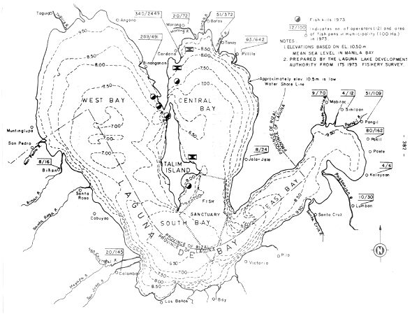
Fig. 1 Laguna de Bay showing the different portions of the lake (after Delmendo and Gedney, 1974)
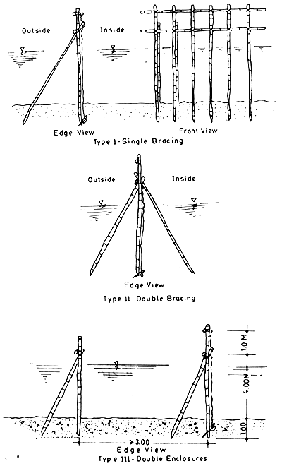
Fig. 2 Types of Framing Arrangement used in the existing fishpen
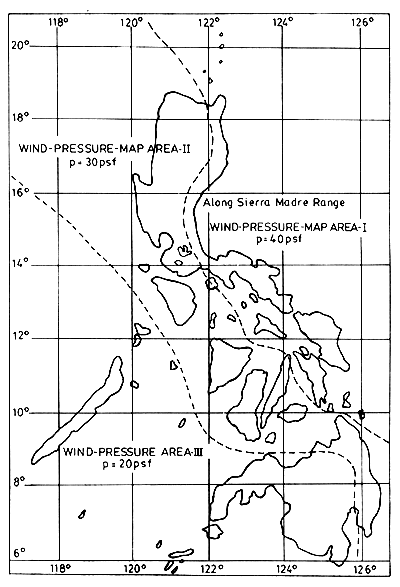
Fig. 3 Wind-Pressure-Map Areas for the Philippines
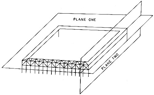
Fig. 4 Planes requiring analysis for lateral forces
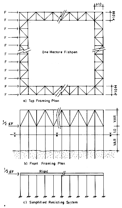
Fig. 5 Design Model One
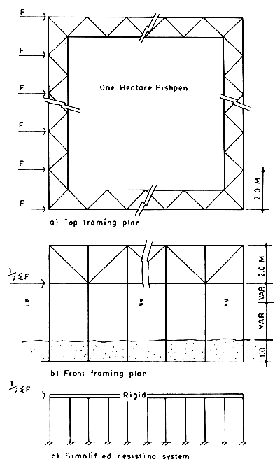
Fig. 6 Design Model Two
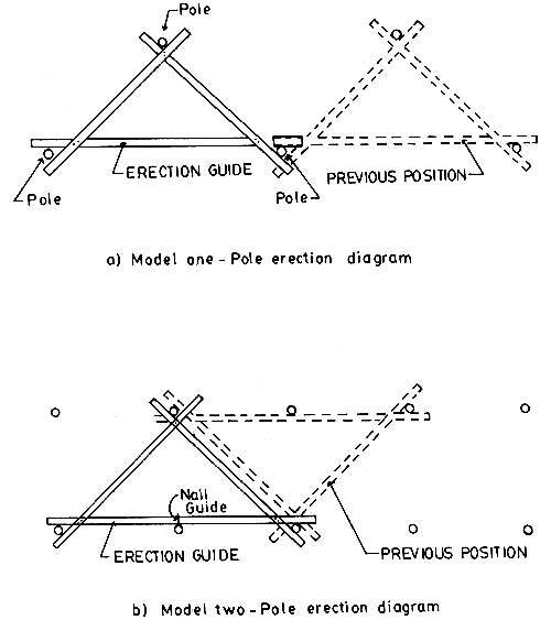
Fig. 7 Pole erection diagram
SCSP-SFDC/77/AEn/CP20
by
B. Tiensongrusmee
Faculty of Fisheries, Kasetsart University
Bangkok, Thailand
and
P. Aguru
National Inland Fisheries Institute, Inland Fisheries Division
Department of Fisheries
Ministry of Agriculture and Cooperatives
Bankok, Thailand
1. INTRODUCTION
Cage culture was initiated in Thailand in early 1950's by fishermen in Uthai Thani province. Initially, they kept the fish in bamboo cage. The cages have been changed subsequently to wooden planks because it is easier to make and to handle. The number of fishermen raising fish in cages increases every year.
1.1 Importance in the country-production and value
Cage culture could play very important roles in enhancing fish production in man-made lake, rivers, and canals. At present, fish production from cage culture is about 227 tons and value about 3 258 Baht (Dep. Fish. 1977).
1.2 Location and species used
Most of cage cultures are operated in Thai Thani Nakornsawan, and Chainat provinces. Species commonly cultured are pla-swai, Pangasius sutchi, and sand goby Oxyeleotris marmorata.
2. DESIGN AND CONSTRUCTION
2.1 Material used
Ideally the cages for fish culture have to be inexpensive, durable and easy to handle. In Thailand, the materials usually utilized are wooden planks, synthetic netting and galvanized wire mesh.
2.2 Sizes, designs and costs
Cages are box-shaped. Its size varies from 2 to 3 m (width) × 5 to 6 m (length) × 1.5 to 2.5 m (depth). Construction cost for standard cage is about 6 000 Baht, and life span is about 14 years.
2.3 Construction and installation
Cages made of wood are constructed by securing together the planks of size 1.5" × 4". Between adjacent planks a space of about 1" is arranged to allow water to pass through. Floatation is aided by bundles of bamboo poles. Cages are secured directly to shore or moored near shore in rivers and tributaries.
3. MANAGEMENT
3.1 Species and stocking rate
Both pla-swai Pangasius sutchi and sand goby, Oxyeleotris marmorata are stocked 100 fish per m2.
3.2 Operation and maintenance
Fry are obtained from natural sources, such as rivers, canals and lakes. At present, Pangasius fingerlings can be obtained from private hatcheries.
Feed utilized depend on the species cultured. Sand goby are fed on trash fish. The supplementary food of fish meal, soy bean, and peanut cakes and rice bran are given occasionally. Pangasius are fed on vegetable, Ipomea aquatica. A mixture of rice bran, cooked paddy rice, cattle and pig manure, and forage fish are also used.
4. CONCLUSIONS AND RECOMMENDATIONS
Cage culture can be considered as an advanced type of aquaculture. Its productivity is 10 to 20 times higher than that of pond culture for comparable input and area. Cage culture has some advantages over pond culture because it eliminates the drawbacks inherent in pond culture such as loss of stock due to flooding, seepage and evaporation of water, problems of excavation of ponds, dependence on soil characteristics, which are not always favourable. In view of this, it is perhaps reasonable to believe that cage culture would be increasingly important to aquaculture and the practice may prevail in the future. Research institutions and organizations which are in charge of the development of aquaculture should, therefore, devote more attention that is now being given to the development of cage culture.
5. REFERENCES
Aguru, P., 1977 Cage culture of pla-swai, Pangasius sutchi Fowler. Nat. Inl. Fish. Inst., In 1. Fish. Div. Dep. Fish., 13p.
Department of Fisheries, 1977 Fisheries record of the production of freshwater fishponds. Dep. Fish., Min. Agric. Coop., Dec. (9): 94p.
Suwanasart, P., 1976 Sand goby culture in Nan river, Changwant, Nakornsawan. Thai Fish. Gaz., 29(1): 51-6
SCSP-SFDC/77/AEn/CP1
by
T.J. Jamandre, Jr.
Western Visayas Federation of Fish Producers, Inc.
Iloilo City, Philippines
1. INTRODUCTION
1.1 Background
If we discuss pumps in general, we shall be talking of a subject that is among the oldest of man's aids, whose origin is lost in antiquity. We do know, however, that these devices provided ancient Egypt, China, Italy, India, Greece, and other ancient civilization with water.
Pumps rank as the second most used industrial device today-electric motor ranking first.
There are pumps that can deliver fluid to heights of several thousand feet while some are built to deliver over a billion gallons per day (over 700 000 gal/min) driven by a 65 000 HP motor. There are pumps designed to deliver at fractional psi (pounds per inch), while others at over 10 000 psi. Pumps come in different sizes, shapes and operating principles such as pistons, impellers, propellers, plungers, gears, screws, rollers, cams crescents, sliding vanes, eccentrics, etc. They come under different construction material such as lead, cast iron, rubber, glass, enamel, stone, copper, different steel aloys, monel stainless steel, concrete, aluminium, bronze, and a host of other materials. Specific designs at times call for pumps for the most volatile materials to the most thick fluids such as molasses, mud, and concrete. Others operate under sub-zero to 1000°F (400°C).
Man himself is provided with a very delicate and highly efficient pump - the heart. It is well-designed and suited for its very purpose.
Most books on pumps go into design rather than operation. Because of our diverse background and training, it is this writer's choice to do away with theories behind pump design. We shall get away from too many formulas and equations as most books on pumps are full of these, for those who want to delve in them. We shall try to limit ourselves to selection and identification of pumps most suited for our purpose, and also learn some typical suggested installations. Hopefully, we shall try to present certain installations to be avoided.
Of the many thousands of pumps available, we shall try to determine what is best suited for our purposes after looking into our own specific needs and conditions of operations.
1.2 Terms used
Our present discussion on pumps for brackishwater aquaculture will take us to discussions of several general terms used in pumps selection, installations and operations, such as:
Suction heads - vertical distance from surface of water to centreline of impeller
Discharge head - vertical distance from surface of water impeller to point of discharge
Total dynamic head - the sum of suction head and discharge head - vertical distance from surface of source of point of discharge
Vortex - movement of liquid in a circular motion
Cavitation - the term refers to conditions within the pump where cavities are formed due to local pressure drop. This is an undesirable condition causing noise and vibration and may cause equipment damage
Hydraulic losses - there are compiled information on losses due to pipe friction, elbow design, sudden enlargement or reduction of channel area
Capacity - volume of liquid pumped - measured in GPM -gallons per minute - may be in cubic metres per hour, can also be in cubic feet per second. Some handy conversion factors:
| 1 cu ft per sec | = | 448.8 GPM |
| 1 000 000 gal/day | = | 694.4 GPM |
| 1 000 barrels/day | = | 29.2 GPM |
| 1 cu m | = | 263 gal |
Efficiency - the degree of hydraulic and mechanical perfection of a pump is judged by its efficiency. It is the ratio of pump energy output to the energy applied (input) to the pump shaft

Efficiency is governed by impeller design, impeller to case clearance, back flow, channel and sump design speeds, cavitationless construction, guide vanes, etc.
Performance curves - vibration of a head with capacity at a constant impeller speed. A complete characteristic includes also efficiency and brake horsepower curves. The vibrations is head, capacity, brake horsepower and speed follow an established rule known as affinity laws. Generally speaking, capacity varies directly with speed. Head varies directly as the square of the speed, brake horsepower varies directly with the cube of the speed.
1.3 Objectives in using pumps
Because of rising cost of fuels (energy) one has to look closely at the cost of pump operation in relation to the organism being cultured and marketed. Pump efficiency is now a very critical factor.
At present, we are very concerned at maximizing production per unit area or volume, be this in tanks or ponds, hence the necessity of pumps for supplementary or total source of water supply. With intensive culture and maximum stocking densities, dissolved oxygen becomes one of the limiting factors, hence, the use of low head large volume pumps to continuously “flow through” new water through the culture ponds. These same kind of pumps are used as aerators and circulation pumps. In almost all aquaculture areas, we construct ponds that are only close to the water or within the tidal range. This make our total dynamic head to be as low as possible and within range of pumps designed for low head, large volume.
2. PUMPS FOR USE IN AQUACULTURE
From studies of pumps, their capacities, energy requirements in relation to our pond requirements of large volumes moved at low heads, we find that three basic designs are very suitable for our purposes and these are: (a) radial flow, (b) mixed flow, and (c) axial flow types of pumps. These are many times called propeller pumps, also called vertical pumps, which is a misnomer because many times these pumps are installed slanting and even horizontally in some cases (Fig. 1).
There are some generalizations that we have for pumps.
Pumps are devices that transfer energy from prime mover to impeller to material (fluid) being moved.
Basically pumps are better suited to push rather than suck. Because of this, efficient installations are those with the least suction head to those with 0 suction head such as submersible pumps and propeller pumps.
2.1 Propeller pumps
2.1.1 Radial flow pump (Fig. 2)
In radial flow pumps the liquid enters parallel to the shaft and is thrown at 90°angle towards the wall of the bell. The energy or force imparted to the liquid is all centrifugal.
Of all the three types of vertical pumps the radial flow delivers the higher head but less volume for the same power. These are normally operated at speeds up to 3 600 RPM - generally higher than the two other pumps.
2.1.2 Mixed flow pump (Fig. 3)
In mixed flow pump liquid enters the pump parallel with the shaft as in the case of radial flow. The liquid is then thrown at an angle of from 40° to 80° of the shaft. Energy imparted is a combination of centrifugal and displacement energy. The hydraulic head range is from 10 to 150 ft (3–45 m) and are available with capacities of over 30 000 GPM. Normal operating speed is usually 1 760 RPM. Said RPM is the usual electric motor RPM making it quite convenient if one has to install this type of pump where electric power is available.
There are now some pump companies that have adopted the mix flow design and made a volute casing type of pump. These makes installation simpler and usually less expensive. However, the sizes are usually limited. This also necessitates foot valves, suction tubes and priming before every operation (Fig. 4).
2.1.3 Axial flow pump (Fig. 5)
In axial flow, liquid enters parallel to the shaft and is discharged in the same direction. All force or energy imparted to liquid is displacement energy. The hydraulic head range of axial flow pumps is from 1 to 20 feet (0.3–6.4 m) per stage. Available in the market are up to half a million (500 000) GPM capacity axial flow pumps. Ideal operating speed is about 1 160 RPM and higher.
From the above we can easily see that the axial flow with TDH of up to 25 feet (7.6 m) per stage easily fall within our range of operation. We only need one stage as we rarely go beyond 10 feet (3 m) TDH.
Of the three, the axial flow has the highest volume for a given power. In most brackish aquaculture applications, a single stage axial flow is sufficient, considering active tidal fluctuations of only 3 to 7 feet (0.9–2.1 m).
We might mention that the design of the impeller blades of the axial flow pumps is gotten from the Gottingen wind tunnel experiments (Fig. 6).
However, on pump application a little bit of error has crept in because in wind tunnel experiments, the air foil travel in straight line while in pump application the motion is rotary. This last decade computerized correction has been instituted, and we now have more efficient axial flow pump impellers.
2.2 Suction pump design
Propeller pumps performance are affected to a large degree by the flow in the suction sump. These are due to high relative velocities short impeller passages, few vanes, and limited guiding action from suction bell. It is necessary to consider (1) strainers and trash rack, (2) spacing of several units, (3) sump intake or flow distribution, (4) submergence, and (5) clearance from floor and walls.
Below is an illustration of a very satisfactory spacing with a uniform approach, also some incorrect designs (Figs. 7 and 8).
Submergence is selected with regards to cavitation limits minimum submergence limits are set to prevent vortexes in suction sump. It is ideal to set the lower edge of the suction bell at 5 feet (15 m) or lower. The minimum allowable should be: the diameter of the suction bell which should not be less than twice the impeller hub or eye to keep the pump self-priming at all times that it is operating.
When vortices appear, these can be checked by providing baffles in the suction sump.
Floor clearances is the free area between the suction bell and the sump floor. It should be at least equal to the area of the bell itself. The illustration below are some clearance dimension that can be helpful for proper sump installations (Fig. 9).
When the intake sump or pit is supplied by a tube, the diameter of the supply tube should be at least two times that of the sump column diameter, with the absolute minimum being 1.5 times that size (Fig. 10).
3. ACCESSORIES AND OTHER DEVICES
In pumps other than self-priming, propeller and submerged pumps, there is need for foot valves. In self-priming pumps the valve is in the pump body itself necessitating very little priming. In some volute centrifugal pumps, priming handpumps and/or tanks are integrated with the pump system during construction.
In pumps of our choice - propeller pumps, one of the accessories is the “gear drive”. This device does three things: (a) change the direction of drive from vertical to horizontal to accommodate most prime movers, (b) serves to change input RPM to the desired or designed pump RPM, and (c) provides auxiliary horizontal drive where there already is a vertical electric motor drive. In some cases these gear drivers are also used to change direction of rotation. However, these gear drives at times cost as much as the pump itself, if not more (Fig. 11).
There are ways of getting away from the use of gear drives. One can install these pumps in a slanting position and have them driven directly by use of cross joints and shaft (Fig. 12).
For the developing countries, one can make an angle drive out of surplus differentials by permanently immobilizing one side of the differential. Different horsepowers can be accommodated as well as different gear ration because of the wide variety of available differentials from cars and trucks and tractors.
In most cases, drive shafts and cross joints, chain and other flexible couplings are chosen over pulley and belts system especially for permanent high horsepower installations where prime mover and pump RPMs are matched.
For brackishwater pump installations we have to consider the corrosive effects of salt water. In some places pump columns are made of either wood or concrete. Because cast iron is less affected by salt water than steel, propeller pumps usually are of cast iron construction.
In some portable propeller pump fabrication, the whole pump assembly is thick-coated with zinc which makes it quite durable and rust resistant. There are also asphalt and epoxy paint jobs at the option of the customer.
Fiberglass pipes are common in brackishwater pump applications. Some pumps are fabricated with fiberglass columns, others with stainless steel.
Below are some illustrations on some useful propeller pumps installations (Fig. 13).
So far we have discussed pumps mostly for having water flow into our ponds.
This writer designed and fabricated a 24" pump with a system of valves (4) so the same pump can be used to water and also dewater the ponds, irregardless of the tide condition prevailing in the supply river. Below is the sketch of said pump (Fig. 14).
In Illustration 14-B, the pump with valves 1 and 3 close and 2 and 4 open, can water the ponds. With valves 1 and 3 open and 2 and 4 close, the pump can dewater the ponds. This writer, by slanting the main pump column, did away with the neccesity of the gear drive, thereby making the total cost of the pump quite reasonable. However, we did find that fabrication of the big valves was quite expensive and operation a bit cumbersome.
As an alternative design, this writer suggests an open supply channel with a system of gates and a swivel discharge pipe for the pump (Fig. 15). This allows for easier repairs and better manipulation. This achieves the same objective of watering and dewatering the ponds at will. By being able to water and dewater the ponds at will, the pond operator can:
harvest his crop when prices are good when others will have to wait for ideal tide situations;
discharge low oxygen water and replenish with new high oxygenated water;
be more flexible allowing greater stocking densities.
It is interesting to note that with this “in and out” pump installation, a lot of heretofore unutilized swamplands, due to their being continuously submerged, can now be used by using the pump to remove low dissolved oxygen water, and to totally drain the ponds for harvesting. The Philippines, as in other countries, have vast amounts of area, both brackish and fresh, under these continuously submerged conditions that can be placed under intensive culture. This is specially important because we are now running out of ideal and suitable areas in the traditional sense of pond construction.
New concepts being put into practice are the following:
pneumatic-driven pumps.
Of late, hydraulic-driven impellers are catching the attention of a number of aquaculture people. This is a system where the prime mover drives a hydraulic pump and transmits the high pressure through hydraulic hoses to drive a hydraulic motor attached to the impeller. One advantage is that the system becomes quite flexible as it does away with long drive shafts that need careful alignment (Fig. 15). It also eliminates obstructions (shaft drive) within the pump column.
Pneumatic driven pumps can be constructed like the hydraulic drive pumps.
From time to time, the military release classified technical information and industry is quick to put same into application. There are now new and better water lubricated bearings that operate under submerged and adverse conditions. Some of these new man-made materials are also developed by industry but a number comes as by-product of space age technology.
Pump makers were fast to apply the variable pitch principles which seem to have been first developed for aircraft. This in turn got into ship's propellers and almost instantly to pumps. For the brackishwater pump applications the performance of the pump is greatly enhanced with variable impellers because of varying TDH with the fluctuation of tides.
In Thailand push pumps are quite common. These are put together with reconditioned automotive diesel engines and long shaft driving an impeller submerged in a tube which pushes water into the tube in the direction opposite that of the power source (Fig. 16, 17). These propellers are usually made to rotate at a third or a fourth of the engine RPM (300 to 500 RPM). Above pumps are usually used to gather shrimp fry from the creek or canal by the pond side from its being supplementary water source for the pond complex. The shrimp seeds are drawn through the pump column and mortalities are estimated to be less than 20 percent due to the low impeller RPM. The gathered fry are then treated with saponin which kills the fish but not the shrimp fry. These are then allowed to enter the rearing ponds for culturing.
4. SUMMARY AND RECOMMENDATIONS
4.1 Summary
It is this writer's view that for brackish aquaculture, the following pumps are suitable in increasing site suitability and improving management, in order:
For economy, it is suggested to go for direct drive of propeller pumps. This will bypass the use of gear drives where in most instances cost as much as the pump itself, if not more. This will, however, necessitate the slanting of the pump column and the engine.
Because of the wide variety of pumps even in just the five categories mentioned above, it is suggested that a qualified technical man be hired to study equipment specifications performance curves, installation situations cost of operations in relation to equipment cost, as to availability of parts and service area to be watered or dewatered.
4.2 Prevailing costs (December 1977)
Some prices that can be helpful (in U.S. dollars) - FOB factory
Fiberglass pipes
| 4" × 20' | US$ 18.50 |
| 6" × 20' | 49.00 |
| 8" × 20' | 61.50 |
| 12" × 10' | 52.70 |
| 16" × 10' | 81.00 |
| 20" × 10' | 131.50 |
| 24" × 10' | 173.00 |
Flexible rubberized tubing
| 6" | US$ 2.10 |
| 8" | 2.55 |
| 12" | 3.55 (per ft) |
| 16" | 4.30 (per ft) |
Diesel engines
For single cylinder, prices range from US$80 to US$120
For multiple cylinder, prices range from US$90 to US$150
Pumps (Volute Type)
Self-priming and mix flow type, range from US$30 to US$60 per inch diameter
Propeller pumps, range from US$70 to US$130 per inch diameter of pump column
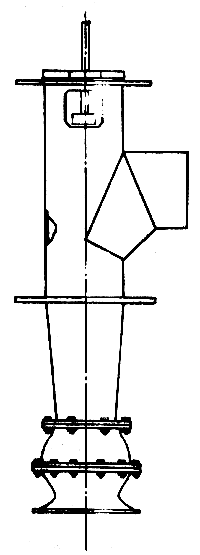
Figure 1. General design of propeller or vertical pumps
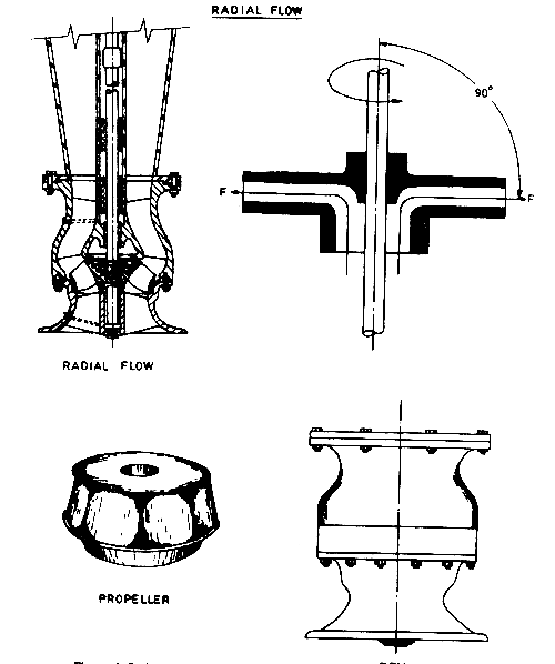
Figure 2. Radial flow propeller pumps
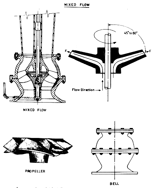
Figure 3. Mixed flow propeller pumps
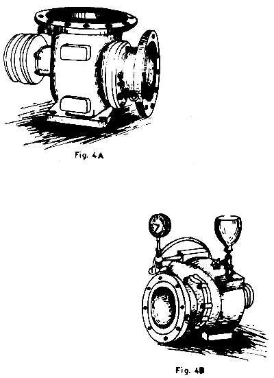
Figure 4. Mixed flow volute type pumps
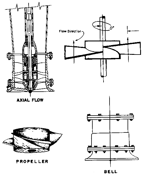
Figure 5. Axial flow propeller pumps
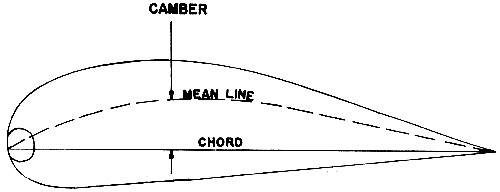
Figure 6. Gottingen wind tunnel model basis for design of impeller blades of pumps

Figure 7. Section pump design showing paper spacing
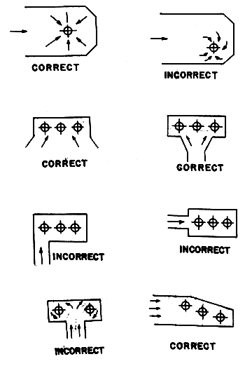
Figure 8. Various correct and incorrect designs for suction pumps

Figure 9. Types of sump installations
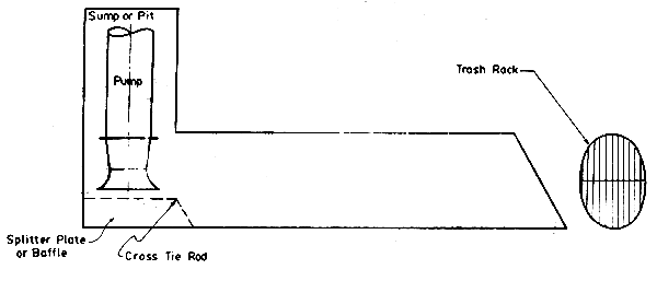
Figure 10. Relative size of supply tube and sump column in suction pumps

Figure 11 - Gear drives for pumps
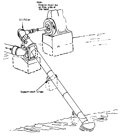
Figure 12-A. Avoiding use of gear drives by using cross joints and shafts

Figure 12-B
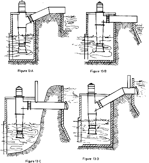
Figure 13 - Types of propeller pump installations
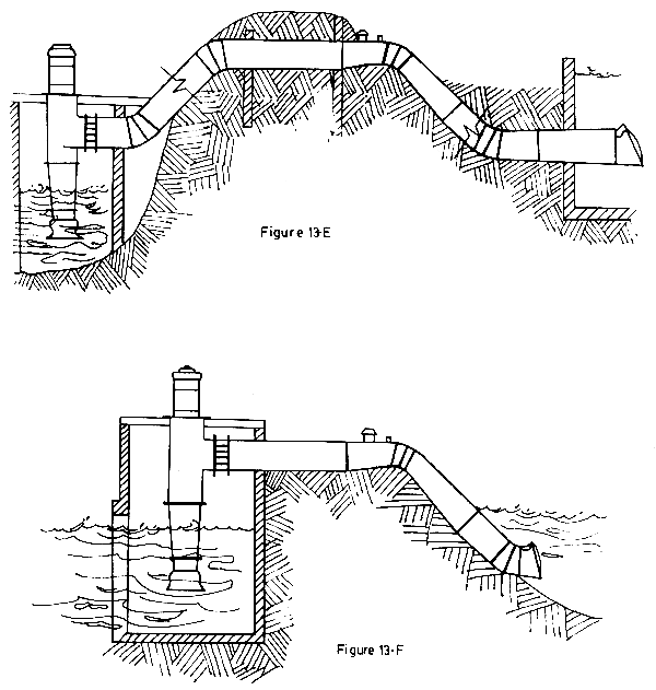
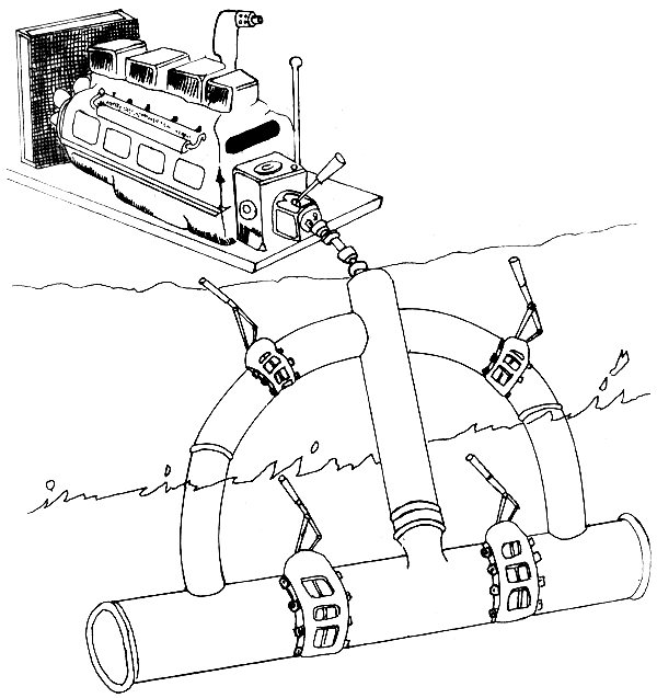
Figure 14. Pump design usable for watering and dewatering ponds
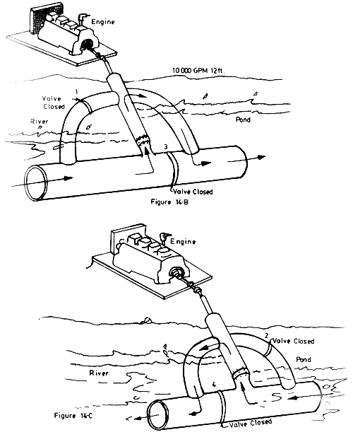
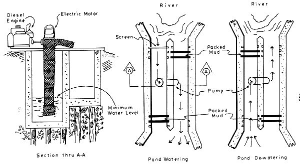
Fig. 15 Main Tidal Gate - with auxiliary pump for electric and diesel engine drive

Figure 16. Typical installations of pushed pumps used in Thailand
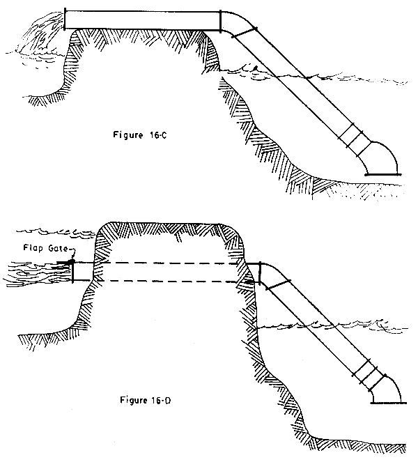
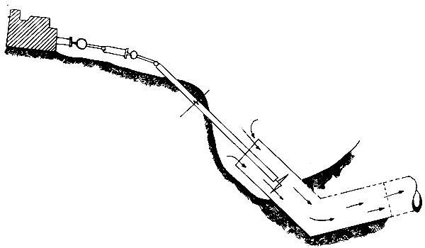
Figure 17. Details of installations of push pumps used in Thailand

Figure 18. Self-priming volute pumps
SCSP-SFDC/77/AEn/CP21
by
S. Tamiyavanich
Department of Marine Science, Faculty of Science
Chulalongkorn University
Bangkok, Thailand
1. INTRODUCTION
One important factor in aquaculture is the circulation and irrigation of water in the pond. Well regulated water not only increases levels of dissolved oxygen but also prevent stagnation of water which may create harmful gas such as hydrogen sulfide. Thus, the environment is unsuitable for rearing any species. Since we cannot depend entirely on nature to irrigate and regulate water into the pond, therefore, we must use pumps to assist this matter. The importance of pumps will be even greater, especially in the culturing of young larvae in particular, the penaeid larvae.
2. TYPES USED AND MANAGEMENT OF PUMPS IN AQUACULTURE
There are three types of pumps used in aquaculture as follows.
2.1 Windmill type
The blades are made of wood and set to catch the wind. The power of the pump is generated by the wind that drives the blades. This particular type of pump depends solely on the wind velocity and its direction. It is still being used in the southern part of Thailand, where the farms are nearer to water source.
2.2 Waterwheel
The wheel is in the trough which is made of wood. Diesel engine is used to drive the waterwheel to pump water into the pond. This type of pump has high capacity. But, because the trough and wheel are quite cumbersome and difficult to build, the waterwheel is not widely used.
2.3 Longtail pump
This type of pump has a pipe that is adjustable to the need. The blades are small and set at the end of the pipe. A diesel motor drives the blades to circulate and pump the water through the longtail pipe into the pond. This type has a very high capacity and is very popular because it is compact and easy to move around. It also saves on diesel fuel. The engine of 90 horsepower can pump water to fill a 50 rai1 farm in 4 hours. But this type of pump also has its drawback because the fast circulating blades kill many young larvae.
3. CONCLUSION AND RECOMMENDATION
The use of the pump in aquaculture has become a necessity, especially in improving the condition of water in the pond. To depend entirely on the nature of tides is not sufficient. Most people prefer to use the longtail type pump. In the future when electricity has reached the rural area, the problem of fuel may be diminished and it may be possible to use electric engines.

Fig. 1. Longtail turbine pump run by engine
1 Rai is a land measure in Thailand equivalent to 1 600 m2
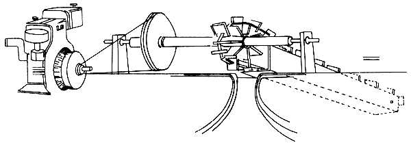
Figure 2. Dragon wheel pump run by engine
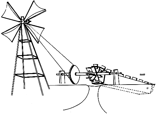
Figure 3. Dragon wheel pump run by windmill
SCSP-SFDC/77/AEn/CP12
by
P.E. Osborn
FAO/UNDP Brackishwater Aquaculture Development and Training Project
Manila, Philippines
1. INTRODUCTION
A few years ago the only fishery users of aeration devices were aquarium operators, fish haulers, and a few fish growers using intensive raceway and tank culture of fish. Aerating devices used in ponds, except in sewage oxidation ponds, were considered as emergency measures and were thought to be of value only for preventing kills due to oxygen depletion. Recently the value of aerating devices has been widely recognized, not only to prevent sudden mortalities, but also to reduce stress and to increase production.
In China, use of aerators (once a day for an hour) has been shown to increase yields by about 14 percent overall, and 28 percent for silver and bighead carp. This increase is presumably brought about by the circulation of nutrients, stimulating plankton growth and by increasing the feeding activity and metabolic rate of the fish (Tapiador, et al, 1977). Agitators are now called “yield-increasing machines” instead of “fish-saving machines”.
In Israel, the first pre-requisite for adopting a regular pond for intensive growth is to ensure a constant oxygen supply for the heavy load of fish, as well as a constant large feed supply. Fish farms have developed various means for supplying air (oxygen) to the pond area during the critical hours of the day, i.e. from early evening till early morning (Rappaport, et al, 1976). The hours of use contrast with use in China, normally two or three hours around noon, or in the morning on overcast days. Other parts of the world consider late night (after midnight) until an hour or two after sunrise to be critical periods.
All aeration devices are designed to increase the amount of dissolved oxygen in the water, or to reduce the amount of other dissolved gases. In either case the same physical laws apply. At any given temperature, salinity and pressure the total amount of any dissolved gas is directly dependent on the partial pressure of that gas in contact with the water.
The rate of exchange of gases with water is partially dependent on the amount of surface area of the gases in contact with the water, and partially on the percentage of saturation of the gases in the water.
One simple method of aerating water is to flow it in a thin sheet over a roughened surface. The thin sheet of water exposes a greater surface to the air, while the roughened surface entrains air bubbles in the water, further increasing the contact area of air and water. Agitation of water will also release dissolved gases which are supersaturated in the water.
Excavating the air over a water surface and replacing it with pure oxygen will increase the partial pressure of oxygen from 21% to 100% and can increase oxygen-content of the water by a factor of nearly 5. This method is sometimes used in fish transport containers.
1.1 Types of aeration devices
We will concern ourselves with mechanical aeration devices designed to speed up the replacement of oxygen in water and which are applicable to pond use. There are three basic types of aeration devices: (i) mechanical agitators which entrain air by surface agitation and sprays, (ii) porous diffusion units which release small air bubbles at a depth, air being delivered from a pump which may be at a distance, and (iii) jet aeration units which depend on entraining air by venturi action as large amounts of water are pumped. There is some overlap and variation in this classification. Some surface agitators may have the impeller at some depth, entrain air through a tube to the surface. and deliver the water to the surface in a spray (Fresh-Flo aerator).
1.2 Efficiency and economy tests
A study was made in the United States using commercial aeration devices of the three types to determine efficiency and economy of pond operation (Mitchell and Kirby, 1976). Aeration devices studied in ponds were:
1.2.1 Viaflo(R) tubing
A porous plastic tube made from DuPont Tyvek(R), twelve lengths of tubing in each pond. Each piece is 1.2 metres long and clamped in a weighted aluminum frame which held the tubing horizontally about 10 cm from the pond bottom. Air was supplied by a Roots blower.
1.2.2 Shutte-Koerting Type 484 water jet exhausters
Units are located near pond bottom in a horizontal position. A pump drawing suction from near the pond centre supplies the water to the exhausters.
1.2.3 Fresh-Flo aerator
1/2 HP Model BE which pumps 1135 liters per minute. A float-mounted device which pumps water through a vertical cylinder by an impeller and discharges this water through a series of slots located above water line.
1.2.4 Air-O-Lator aerators
Two sizes: a 1/3 HP, Model AF-12, and a 1 HP, Model S-1. This is a propeller type device which picks up near-surface water and discharges it against a cone to create a circular spray pattern with turbulence.
Normal pond procedure was to measure temperature and dissolved oxygen concentration at hourly intervals from 8 PM to 3 AM with aeration system off. At 3 AM aeration was turned on and readings taken every 30 minutes until 6 AM. Measurements were taken near the surface and at the bottom in 3 different locations. The total of the six readings were averaged.
2. RESULTS
Oxygen transfer and economy of various aeration devices1
| Device | Oxygen transfer Kg/hr | Kg 02/kw-hr |
| Air-O-Lator | ||
| 1 HP | 1.15 | 0.48 |
| 1/3 HP | 0.50 | 0.50 |
| Fresh-Flo (1/2 HP) | 0.24 | 0.24 |
| Viaflo(R) tubing | 0.29 | 0.96 |
| Jet exhausters (Ave.) | 0.80 | 0.28 |
1 02 content = 50% of saturation, temperatures = 25°C, 0.066 ha pond (pond volume = 590 m3)
Economics of pond aeration
Basic: Installation of equipment to provice 1.15 kg 02/hr
to a 0.66 ha pond 1.07 m deep
| Device | Initial installed cost, (US$) | Yearly operating cost (US$)1 | Present worth of total cash outlay2 |
| Air-O-Lator | |||
| 1 HP | 600 | 1 400 | 9 340 |
| 1/3 HP | 900 | 1 370 | 9 290 |
| Fresh-Flo | 2 200 | 2 850 | 19 700 |
| Jet exhauster | 4 400 | 4 300 | 30 600 |
| Viaflo(R) | 5 100 | 700 | 9 400 |
1 Operation 6 hours/day, 300 days/years; power cost = 3 ¢/kw-hr
2 10-year operating life; 10% interest rate
3. CONCLUSIONS AND OBSERVATIONS
The authors of the test concluded that the Air-O-Lator devices were effective and economical. Other advantages were relatively inexpensive first cost, and easily movable. Mobility is of particular value in multiple pond type operations. One possible disadvantage was disruption of the pond bottom under the aerator in depths of water less than 70 cm.
Viaflo (R) tubing was the most energy-efficient system tested. It has disadvantage in requiring complex and expensive piping and compressor systems, and requires considerable maintenance. During periods of inactivity considerable algae growth appears on the tubing surface requiring hand cleaning.
The Fresh-Flo agitator was not nearly as efficient as the Air-O-Lator. The jet exhauster do a good job of oxygen transfer, but have high energy consumption and are not as mobile as the floating agitators.
3.1 Test of aeration devices in Israel in 1975
Similar tests to the one previously described were conducted in carp ponds in Israel and described by Rappaport, et al, 1976. In addition to measuring the percent of oxygen saturation, the tests attempted to correlate fish growth with various systems of aeration.
Devices used were:
| (a) | Blower and plastic piping | - | compares to Viaflo(R) tubing |
| (b) | Injector (venturi method) | - | same as jet exhausters |
| (c) | Floating aerator | - | Fresh-Flo agitator |
| (d) | Standard Blower | - | air delivered at single point - no diffuser |
| (e) | “Japanese Water Mill” | - | paddles lift water into air and circulate water around pond |
Average percentage of oxygen saturation at sunrise in 0.02 ha ponds with a stocking of 7 250 to 11 380 kg/ha, May-July 1975
| (a) | Japanese Water Mill | 0.25 HP | 68% |
| (b) | Floating aerator | 0.33 HP | 67% |
| (c) | Plastic tubes | 34% | |
| (d) | Standard blower | 17% | |
| (e) | Injector | 12% |
It can be seen that the 1/4 HP “Japanese Water Mill” was at least as effective as the 1/3 HP floating aerator.
Growth of fish
A check for a possible correlation between the mean oxygen level at sunrise and the yield of fish reveals that in the two groups of ponds with the blower and injector the yield decreased by almost 44% as compared to the largest yield (floating aerator). The difference in yields for other methods were not especially significant.
Total increment of carp with various types of aeration
| Plastic | Japanese | Floating | Standard | ||
| Types of aeration | |||||
| tubes | Injector | watermill | aerator | blower | |
| Days of growth | 140 | 141 | 142 | 81 | 147 |
| Total increment, kg/ha | 11 730 | 9 020 | 12 150 | 8 400 | 11 600 |
| Ave. increment per ha/day, kg | 83.8 | 64.0 | 85.6 | 103.7 | 78.9 |
| Calc. increment 200 days kg/ha | 16 760 | 12 800 | 17 120 | 20 740 | 15 780 |
| Feed conversion ratio | 3.8 | 3.3 | 3.9 | 3.8 | 4.1 |
| Percent 02 saturation at sunrise | 27–50 | 11–27 | 60–84 | 63–67 | 17–39 |
| Yield relative to highest | 81 | 62 | 83 | 100 | 76 |
NOTE: The experiments with the floating aerator were conducted only from the end of July to the end of October. The absence of data for the early growing season, when fish were small, exaggerate a little the calculated increment for 200 days of growth.
3.2 Summary of Israel test
Measurements of oxygen saturation at sunrise have shown that installations which move pond water by pumping lower layers and spraying them over the pond surface are more efficient than those which inject air into water.
The influence of low oxygen concentrations at sunrise on fish growth were evident only when saturation was below 25% (at water temperatures of 20–25°C).
4. DISCUSSION
While air stones and air lifts are valuable in aquaria and hatcheries, they are not discussed here. Air lifts are to be discussed in conjunction with other papers in this workshop. Discussion has been largely limited to pond application of aerating devices.
Aeration will become increasingly important if aquaculture moves from extensive or semi-extensive management to very intensive management.
The attitude towards the use of aeration devices has changed radically during the past few years.
We can expect development of more efficient devices at lessened costs as use becomes widespread.
Aeration devices, agitators, are presently commercially available for tanks in sizes from 1/20 to 1 HP. They are also available for small containers powered by standard flashlight batteries.
Floating pond aeration devices are available powered by electric motors or gasoline engines. Engines can be mounted on the device or on shore with the paddle wheel activated by a power transmission rod.
A careful survey of requirements should be made before investing in any particular type or size of aeration device.
5. REFERENCES
Mitchell, R.E. and A.M. Kirby, Jr., 1976 Performance characteristics of pond aeration devices. Proc. Ann. Meet. World Maricult. Soc. 7: 561–81
Rappaport, A., S. Sarig and M. Marek, 1976 Results of tests of various aeration systems on the oxygen regime in the Genosar experimental ponds and growth of fishes there in 1975. Bamidgeh, 28 (3) : 35–49
Tapiador, D.D., et al, 1977 Freshwater fisheries and aquaculture in China. FAO Fish. Tech. Pap. (168): 84p.