CHAPTER 1
DEFINITION AND SCOPE OF PROTECTIVE MEASURES FOR ROADS
1.1 General Introduction
This handbook was written as a guide to reducing environmental impacts of forest roads in mountain watersheds and is intended to be used by professional land managers involved in decisions regarding upland conservation, watershed management, and watershed rehabilitation. Its purpose is to (1) identify potential threats to water quality from the construction and maintenance of roads, and (2) recommend procedures, practices, or methods suitable for preventing, minimizing, or correcting erosion problems. It discusses proper planning, reconnaissance, road standard development, erosion control, slope stabilization, drainage design, and maintenance techniques as well as cost analysis procedures that can be applied in the design, construction, and maintenance of forest roads. Specific questions relating to road design procedures, general layout and construction methods can be found elsewhere, and it is left to the reader to locate sources for that type of information.
The types of roads considered here would generally be built to withstand low to moderate traffic levels for purposes of providing access for residents, timber harvesting, reforestation, rangeland management, and other multiple use activities where access to upland areas is required. Availability of some basic heavy equipment, such as bulldozers and graders, is assumed. Whenever possible, emphasis will be given to labor- rather than machinery-intensive methods. However, livestock or human labor may often be substituted wherever machines are mentioned and may in fact be preferable to the use of machines by reducing environmental impacts during operations. This is especially true in the case of road maintenance. Production rates in most cases will be much slower and should be considered when developing cost estimates.
Much of the information cited here reflects years of research and experience gained from various sources. As such, the material presented must lie evaluated in light of local geographic, economic, and resource needs; it cannot and should not be a substitute for regional knowledge, experience, and judgment.
1.2 Interaction of Roads and Environment
Forest roads are a necessary part of forest management. Road networks provide access to the forest for harvests, for fire protection and administration, and for non-timber uses such as grazing, mining, and wildlife habitat. New road construction is required to enter previously uninhabited areas or underutilized lands, and will continue to provide access in order to properly manage those lands.
Construction and use of forest roads result in changes to the landscapes they cross. Of all the types of silvicultural activities, improperly constructed and inadequately maintained "logging roads" are the principal human-caused source of erosion and sediment. (US Environmental Protection Agency, 1975) Road failures and surface erosion can exert a tremendous impact on natural resources and can cause serious economic losses because of blocked streams, degraded water quality, destroyed bridges and road rights-of-way, ruined spawning sites, lowered soil productivity, and property damage.
Erosion is related, among other things, to:
-
Physical factors. These would include soil type, geology, and climate (rainfall).
-
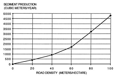
Road density. The total length of roads per unit area of watershed is termed road density. Erosion rates are directly related to the total length of roads in a watershed, as shown in Figure 1. A road network of approximately 30 to 40 m/ha is considered optimal for most management purposes.
-
Road location. The location of the road in relation to slope, stream channels, and sensitive soils has a direct effect on the amount of sediment reaching the stream.
-
Road standards and construction. Designed road width, steepness of cut banks or road fills, methods of construction, and drainage installations will directly affect the area of disturbance and potential for failure following road construction.
Figure 1. Sediment production in relation to road density (Amimoto, 1978).
Causes of erosion may include: (1) removal or reduction of protective cover, (2) destruction or impairment of natural soil structure and fertility, (3) increased slope gradients created by construction of Put and fill slopes, (4) decreased infiltration rates on parts of the road, (5) interception of subsurface flow by the road cut slopes, (6) decreased shear strength, increased shear stress, or both, on cut and fill slopes, and (7) concentration of generated and intercepted water. (Megahan, 1977)
The severity of the impact is closely related to the overall land surface exposed by roads at a given time, the drainage density of the watershed (degree to which stream courses dissect the land), slope (gradient, length, shape, and position on the slope), geologic factors (rock type, strength, and hardness, bedding planes, faulting, subsurface drainage), and climate. Generally, the greater the intensity of storm events and the more drainage dissects the landscape, the more acute the necessity to plan for avoiding water quality impacts in constructing and stabilizing roads. In central Idaho, Megahan and Kidd (1972) observed sediment production rate increases of 770 times per unit area of road prism for a six year study period. Although surface erosion following road construction decreased rapidly with time, the major impact occurred from one road fill failure after a single storm event. Other research in the region points to mass failures as the Most serious erosion process contributing to reduced water quality on forest lands. (Swanson and Dyrness, 1975; Fredriksen, 1970; Dyrness, 1967; Megahan, 1967)
It is well documented that water quality impacts caused by roads can best be dealt with by prevention or by minimizing their effects, rather than attempting to control damage after it has occurred (Brown, 1973; Megahan, 1977). This can best be done by minimizing the total mileage of roads through proper planning, properly locating roads in relation to topography and soils, minimizing exposed constructed road surfaces by proper road standard selection and alignment, and using proper road construction and culvert installation techniques.
Additionally, these same researchers have found that the majority of sediment generated on roads occurs within the first year following construction. This would emphasize the need for concurrent erosion control measures during and immediately following construction. Merely seeding bare soil surfaces may not be sufficient to curb soil erosion.
1.3 Erosion Processes
Recognition of the type of erosion occurring on an area and knowledge of factors controlling erosion are important in avoiding problem areas and in designing control structures. Erosion can be broadly categorized as surface erosion and mass erosion. Mass erosion includes all erosion where particles tend to move en masse primarily under the influence of gravity. It includes various types of landslides and debris torrents. Surface erosion is defined as movement of individual soil particles by forces other than gravity alone such as overland flow or runoff, raindrop impact, and wind. Dry creep or dry ravel, the movement of individual particles resulting from wetting and drying, freezing and thawing, or mechanical disturbance, is considered a surface erosion process.
Surface erosion is a function of three factors: (1) the energy available from erosion forces (raindrop splash, wind, overland flow, etc.), (2) the inherent erosion hazard of the site (soil physical and mineralogical characteristics, slope gradient, etc.), and (3) the amount and type of cover available to protect the soil surface (vegetation, litter, mulch, etc.). Mass erosion is controlled by the balance between stabilizing factors (root strength, cohesion) and destabilizing factors (slope gradient, seepage forces, groundwater) operating on a hillslope. Another way of stating this relationship is the relative magnitude of shear strength versus shear stress. When shear stress is less than or equal to shear strength, the slope will remain stable; when stress exceeds strength, the slope will fail.
Factors that might be considered when assessing the impact of road construction and subsequent development of a site might include:
Soil and Geology
- soil - physical and chemical characteristics
- geologic conditions (stratigraphy, mineralogy, etc.)
- groundwater occurrence and movement
- slope stability
- seismic characteristics
Climate and Precipitation
- start and end of rainy season
- intensity and duration of storms
- occurrence of summer storms
- seasonal temperature
- frost-free period
- wind erosion
- snow melt runoff
- rainfall runoff before and after development
Topography
- slope angle
- slope aspect
- slope length
- density and capacity of drainageways
- suitability of sites for sediment basins
Vegetative Cover
- type and location of native plants
- fire hazard
- ease in establishing vegetative cover
- adequacy of existing plants in reducing erosion
Manner of Development
- percent grade and layout of roads
- density of roads
- distribution of open space
- structures affecting erodible areas
- number of culverts, stream crossings
- size of areas, duration and time of year when ground is left bare
1.4 Assessment of Erosion Potential
1.4.1 Surface Erosion
Soil properties important in the evaluation of a site for its resistance to erosion include particle size, permeability, water retention characteristics, compressibility, shear strength, void ratio or porosity, shrink-swell potential, liquid limit and plasticity index. Soil developmental characteristics such as horizonation, depth to bedrock or parent material, and depth to seasonal water table are also helpful. Other factors which influence - erodibility include vegetation characteristics (foliage density, height above soil surface, rooting characteristics) and litter cover. Raindrop energy may be partially dissipated by overstory or understory vegetation, thereby reducing the amount of energy transmitted directly to the soil surface. The lifter layer contributes the most in protecting the soil from erosion by absorbing the net energy that finally reaches the surface after filtering through vegetation canopies. Any surface runoff that may occur on a natural soil surface will generally take place below the litter layer, however, the flow velocity is very slow because of the tortuosity of the path that the water must take to pass through the litter. Particle detachment, therefore, is unlikely where good litter cover is present.
In order to discuss soil characteristics in a uniform and accurate manner, several classification systems have been developed which provide guidance in identifying a particular soil's desirability or value for various engineering uses. The Unified Engineering Soil Classification system was developed as a method of grouping soils for military construction and is shown in Table 1. -Other classification systems include the United States Department of Agriculture Soil Textural Classification system and the American Association of State Highways and Transportation Officials (AASHTO) system.
A guide for evaluating soil erosion potential in the field can be made by visual inspection of the soil and by such techniques as shaking, patting, and kneading. Subsurface samples can be extracted with the use of hand augers or shovels. Classification of soils into erodibility groups based on the the Unified System is presented in Table 2. A discussion of erodibility in relation to cross-drain spacing requirements is presented in Chapter 3.4.3.
Several methods are available in order to evaluate the potential for soil loss from surface erosion, and two different approaches have been utilized in estimating surface soil loss. The first of these is empirical in nature using predictive equations developed from analysis of "real" data. The second consists of the use of process models developed through analysis of cause and effect relationships. The empirical procedure most commonly used is the Universal Soil Loss Equation (USLE) which was originally developed for use on midwestern United States agricultural soils and has since been modified for use in forest environments. The Modified Soil Loss Equation (MSLE) uses a vegetation management factor (VM) to replace the cropping factor (C) and the erosion control practice factor (P) used in the USLE (U. S. Environmental Protection Agency, 1980). The MSLE is:
A = R K L S VM
where:
A = estimated average soil loss per unit area in tons/acre for the time period selected for R (usually one year)
R = rainfall factor; usually expressed in units of rainfall erosivity index (El) and evaluated from an iso-erodent map
K = soil erodibility factor, usually expressed in tons/acre/EI units for a specific soil in cultivated continuous fallow, tilled up and down the slope
L = slope length factor expressed as the ratio of soil loss from the field slope length to that from a 72.6 foot (22.1 meter) length on the same soil, gradient, cover, and management
S = slope gradient factor expressed as the ratio of soil loss from a given field gradient to that from a 9 percent slope with the same soil, cover, and management
VM = vegetation management factor expressed as the ratio of soil loss from land managed under specific conditions to that from the fallow condition on which the factor K is evaluated.
Numerical values for each of the factors are based on research data and differ dramatically from one region to another, from one locality to another, and even from one field to another. However, approximate values for potential soil loss from a site may be calculated with the understanding that strict adherence to the assumptions made in selecting values for individual factors is required if a reasonable answer is to be obtained. Even so, errors in the range of an order of magnitude of the true erosion rate are not uncommon. A procedural guide in using the MSLE is presented in Chapter IV, An Approach to Water Resources Evaluation of Non-Point Silvicultural Sources, US Forest Service, 1980.
Table 1. Unified Soil Classification System (adapted from U.S. Department of the Interior, Bureau of Reclamation, Earth Man Manual, Denver)
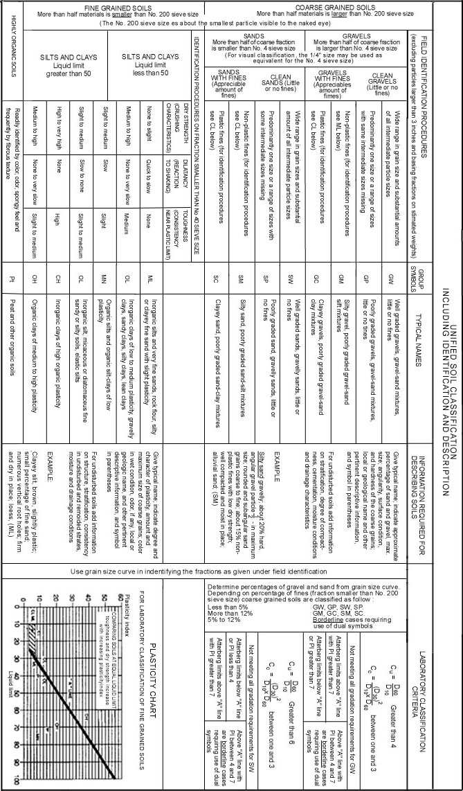
Boundary classifications: Soils possessing characteristics
of two groups are designated by combination of group symbols. For example
GW-GC, well graded gravel-sand mixture with clay binder.
All sieve sizes on this chart are U.S. standard.
ADOPTED BY CORPS OF ENGINEERS AND BUREAU OF RECLAMATION - JANUARY 1952
Unified Soil Classification Chart (Sheet 1 of 2) From drawing no. 103-D-347.
Table 2. Guide for placing common soil and geologic types into erosion classes. (Forest Soils Committee of the Douglas-fir Region of the Pacific Northwest, 1957).
|
Erosion Class |
I |
II |
III |
IV |
V |
VI |
VII |
VIII |
XI |
X |
|
Erosion Index |
10 |
20 |
30 |
40 |
50 |
60 |
70 |
80 |
90 |
100 |
|
Standard soil textures and unified system soil groups |
SM |
SM |
Silt (uncon-solidated) (B) |
Silt (uncon-solidated) (B) |
Silty clay loam A) |
clay loam A) |
Loamy sand (C) |
Coarse sand (C) |
Fine gravel (C) |
Rock (C) |
|
ML |
SL |
OL |
OL |
Silty clay (A) |
Silt loam (A, B) |
Sandy loam (B) |
SW |
SW |
Cobble (C) |
|
|
MH |
MH |
Clay, varying with type, cohesiveness and compaction (A) |
SP |
SP |
Gravel (C) |
|||||
|
CI |
Sandy clay (B) |
Sandy clay Loam (B) |
Sand (B, C) |
GW, GP |
||||||
|
SC, GM OH, CH |
CH, GM |
GC |
||||||||
|
Special cases; General names and descriptions. |
Decomposed granodiorite (C) |
Decomposed sandstone, e.g. (B, C) |
Fine soils derived from rocks high in mica, (C) |
Coarse soils derived from rocks high in mica (C) |
Some volcanic ash or extremely fine pumice sometimes difficult to distinguish from residual soils (B) |
Fractured loose basalt or shale (C) |
||||
|
"Shot" as found in "shot-loam"
(B, C)
|
||||||||||
|
Highly decomposed granites (C) |
Moderately decomposed granites (B) |
Greasy decomposed rock high in clay (A) |
Coarse volcanic cinders (C) |
|||||||
|
Pumice, varying with location, particle Size, denisty, topography, and compaction (B, C) |
||||||||||
|
* Erosion classes rate the soil testures and geologic types listed
as if they contained 100 percent of the material specified. To place
a soil mixture in the proper erosion class, multiply the estimated
percent content of the various "Components" (rock, cobble, gravel,
etc. and a given soil texture) by their respective erosion indices
and add the results. The total indicates the erosion class of the
mixture. (See text for examples) |
1.4.2. Mass Soil Movement
Accurate models and data needed to predict mass soil movement over broad areas are currently lacking. A widely used technique involves the relatively simple planar infinite slope analysis described by Sidle (1985). This method is particularly useful when the thickness of soil is small in comparison to the length of slope and where the failure plane parallels the soil surface. The infinite slope model is illustrated in Figure 2 .
Figure 2. Infinite slope analysis for planar failures.
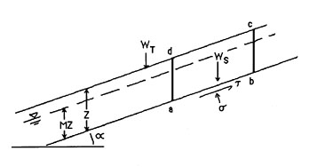
The forces acting on the soil mass "a b c d" in Figure 2 include the vegetative weight per unit area, WT, and the weight of soil WS which give rise to the tangential and normal shear stresses acting on line a-b. The height of the water table is MZ. The vertical height of water above the slide plane, designated M, is a fraction of the soil thickness, Z, above the plane.
The resistance to failure or shear strength S along line a-b is:

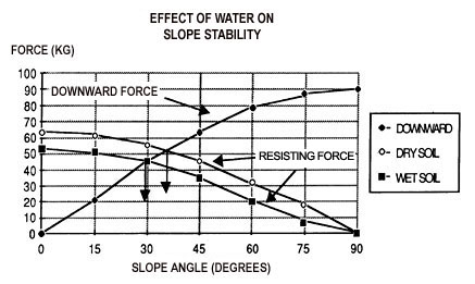
Theoretically, the factor of safety represents a ratio of forces causing a slope to remain stable (shear strength) to forces causing it to fail (shear stress). A factor of safety greater than 1.0 implies a stable slope, while a value less than 1.0 suggests the potential for a slope failure. Figure 3 illustrates the relationship between frictional resistance and the downslope component governing the disposition of a 45 kg (100 lb) block on uniform dry sand. For slope gradients greater than 70 percent, the block will slide because the driving force (E) is greater than the frictional resistance (F) to sliding. Frictional resistance for a normal soil at the plane c d is a function of soil, geology, and moisture content of the soil, and root strength.
Soil cohesiveness tends to prevent movement and generally increases with increased weathering producing finer textured soil particles. However, relative cohesion will decrease as soil moisture content increases causing the block a b c d to "float" above the failure plane c d. As a dry soil absorbs water, its shear strength decreases because water films tend to separate soil particles. This, in turn, reduces the cohesive strength produced by the frictional and electrical forces which cause clay particles to attract each other and form aggregates. An additional force component, buoyancy, tends to nullify the interlocking forces of soil particles which contribute to stability. The uplift force of groundwater is equal to 93.1 kg/m (62.4 lb/ft) of water in the soil. The effective normal force is equal to the weight of soil resting on the surface minus the uplift force of the groundwater. Figure 4 shows the effect of adding 15.2 cm (6 in) of water to 0.6 m (2 ft) of soil (again, dry sand). The effective normal force is reduced significantly by the addition of water resulting in failure when slopes equal or exceed 58 percent.
Figure 3. Relationship between frictional resistance (F) and driving force (E) promoting downslope movement. (Burroughs, et al., 1976).
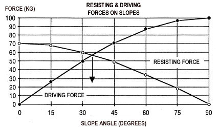
Figure 4. Sixty cm of soil with 15 cm of ground water will slide when the slope gradient exceeds 58 percent. (Burroughs, et al., 1976).
The problems and limitations in applying this or similar models are many. Estimation of these factors is extremely difficult given the high degree of anisotrophy and heterogeneity of soil properties. Detailed analysis of factors leading to failure of natural slopes, especially piezometric information, is lacking. As difficult as the prediction of the factor of safety is, predicting the course or type of deformation a failure will take is far more difficult. The contribution of plant root systems in reinforcing the soil matrix is often significant but difficult to quantify.
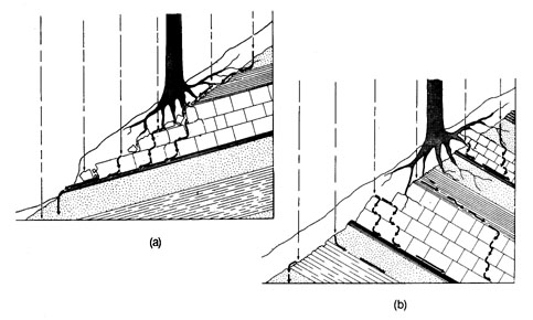
The orientation of the underlying geologic strata plays an important part in overall stability. When bedding planes are oriented in the direction of the slope (Figure 5a), potential zones of weakness and failure surfaces are ready-made. Additionally, the beds will tend to concentrate subsurface water and return it to the surface. Any excavation on such slopes may also remove support and create excessive road maintenance problems by rock and soil sliding on to the road. Conversely, geologic strata which are more or less normal to the surface slope (Figure 5b) resist sliding since weakness in the bedding planes do not contribute to the downslope component nor do they concentrate percolating rainwater near the surface.
Figure 5. (a) Subsurface rainwater flows in the direction of the slope when geologic strata dip toward the slope. (b) Subsurface rainwater percolates downward and out of the root zone when geologic strata dip in that direction (Rice, 1977).
Other factors influencing slope stability include seepage forces exerted by groundwater a it moves downslope through the soil and support provided by live tree roots in contributing to soil strength. Although not fully understood, the presence of root strength is most important where soils are shallow and where winter storms can cause groundwater levels to rise sharply. Roots tend to anchor shallow soils on steep slopes to fractures in the underlying rock. Reports from U Forest Service researchers in Alaska indicate that the number of landslides from cut-over area increases within 3 to 5 years after logging-about the time when root decay becomes nearly complete. (Bishop and Stevens, 1964) Researchers in Japan and the U. S. have found that roc systems of different species have differing decay rates. Rice (1977) postulates that harvest scheduling according to relative contribution of a particular specie's root system to slope stability might provide additional support to slopes at or near threshold strength values.
LITERATURE CITED
Amimoto, P.Y. 1978. Erosion and sediment control handbook. California Division of Mines and Geology, Department of Conservation. 197 p.
Brown, G. W. 1980. . Forestry and Water Quality. School of Forestry, Oregon State University. 124 pp.
Burroughs, E. R. Jr.,G. R. Chalfant, and M. A. Townsend. 1976. Slope Stability in Road Construction. US Department of the Interior, Bureau of Land Management, Oregon State Office. 102 pp.
Dyrness, C. T. 1967. Mass soil movement in the H. J. Andrews- Experimental Forest. USDA Forest Service, Research Paper PNW-42. 12 pp.
Fredriksen, R. L. 1970. Erosion and sedimentation following road construction and timber harvest on unstable soils in three small western Oregon watersheds. USDA Forest Service Research Paper, PNW-104. 15 pp.
Megahan, W. F. 1967. Summary of research on mass stability by the Intermountain Forest and Range Experiment Station soil stabilization project. In: Proc. USDA For. Serv. Berkeley Mass Erosion Conference.
___________1977. Reducing erosional impacts of roads. In: Guidelines for Watershed Management. Food and Agriculture Organization, United Nations. Rome. p 237-261.
Megahan, W: F. and W. J. Kidd. 1972. Effect of logging roads on sediment production rates in the Idaho Batholith. USDA Forest Service Research Paper, INT-123. 14 pp.
Rice, R. M. 1977. Forest management to minimize landslide risk. In: Guidelines for Watershed Management. Food and Agriculture Organization, United Nations. Rome. p 271-287.
Swanson, F. J. and C. T. Dyrness. 1975. Impact of clear-cutting and road construction on soil erosion by landslides in the western Cascade Range, Oregon. Geology 3(7):393-396.
Sidle, R. C., A. J. Pearce, and C. L. O'Loughlin. 1985. Hillslope stability and land use. Am. Geophys. Un., Wat. Res. Mon. No. 11. Washington, D. C. 140 pp.
US Environmental Protection Agency. 1975. Logging roads and protection of water quality. EPA 910/9-75007. 312 pp.
US Department of Agriculture, Forest Service. 1980. An Approach to Water Resources Evaluation of Non-Point Silvicultural Sources (A Procedural Handbook). Interagency Agreement No. EPA-IAG-D6-0660. 772 pp.