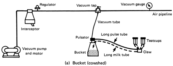
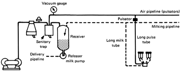
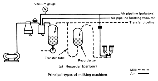
The basic layout of the three main types of milking machines are the same. Each has a pump to remove air from the vacuum pipeline, a vacuum regulator and a container to collect the milk that comes into the teatcup assembly during milking.
(b) Milking pipeline (cowshed and parlour)
MILKING MACHINES AND EQUIPMENT
The principle of machine milking is to extract milk from the cow by vacuum. The machines are designed to apply a constant vacuum to the end of the teat to suck the milk out and convey it to a suitable container, and to give a periodic squeeze applied externally to the whole of the teat to maintain blood circulation.
A milking machine installation consists of a pipework system linking various vessels and other components which together provide the flow paths for air and milk. The forces necessary to move air and milk through the system arise from the fact that it is maintained at a vacuum. Thus it is atmospheric pressure which forces air, and intra-mammary milk pressure which forces milk, into the system and the combination of these forces causes flow. To be a continuous operation it is necessary to remove air and milk from the system at appropriate rates.
Although milking machines have now developed into systems that show considerable diversity they have the same basic components. The air is removed by a vacuum pump at a constant rate. In a bucket or direct-to-can machine milk is removed from the system by disconnecting the milk container; in milking pipeline and recorder machines the milk is removed by a milk pump or releaser.
Fig. 1 shows the flow of air and milk through three basic types of machine during normal milking. In the bucket (or direct-to-can) machine the milk enters the teatcups and travels through the short milk tubes to the claw where air is admitted and the milk and air travel along the long milk tube to the bucket (or can). The milk remains in the bucket (or can) and the air separates to pass up the vacuum tube to the vacuum pipeline. The pulsator which is usually fixed on the bucket lid admits air intermittently and this passes along the long pulse tube to the teatcup chambers. To control the vacuum at a predetermined level air is also admitted to the system through a vacuum regulator which is fitted on the vacuum pipeline near to the milking points.
VACUUM AND MILK FLOW
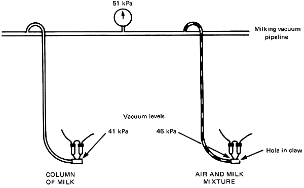
When the milk from the claw is raised to a pipeline this can markedly reduce the vacuum at the teat because of the weight of milk in the long milk tube. The reduction in vacuum can be much reduced by bleeding air through a small hole in the clawpiece
In addition to the designed sources of air admission, air can be drawn into the teatcups past the teat and also when a milk container is changed or emptied. In a poorly maintained machine there may also be inward leakage of air at joints or points of damage. To maintain the working vacuum the vacuum pump extracts the air admitted into the system by compressing it so that it can be discharged to atmosphere.
In pipeline milking machines the flow pattern is similar to the bucket machine except that milk and air from each claw flow either directly to a recorder vessel where air and milk are separated, and/or through the milking pipeline to a common receiver vessel where milk and air are separated. There is no further air admission at this point when a motor driven releaser milk pump is used to empty the receiver. Other types of releaser (eg. pulsator controlled spit chamber and double chambered weight operated) admit air.
Where air and milk are transported together the flow pattern becomes complex depending on various factors particularly the volume of air relative to milk or air:milk ratio. Air is normally admitted in to the claw at a rate of 4 to 8 l/min. A milk flowrate for a fast milking cow will be about 6 l/min, giving an air:milk ratio of 0.7:1 to 1.2:1. Towards the end of milking when the milk flowrate has decreased to 0.25 l/min the ratio becomes 16:1 to 32:1.
The air:milk ratio becomes important where milk has to be elevated from the claw as in milk pipeline and recorder machines other than those with low level milk pipelines. Elevating a liquid, as distinct from a gas, involves a loss of potential energy and this is compensated for by a change of vacuum. Thus elevating a column of milk in a vacuum system through 1 m height reduces the vacuum by about 10 kpa. Therefore if the vacuum at the top of the column is 51 kpa it will be only 41 kpa t the bottom. This vacuum drop is markedly reduced by the admixture of air. If the air:milk ratio is 1:1 the weight of milk in the column is halved and the vacuum drop becomes only 5 kpa; if it is 9:1 the vacuum drop is only 1 kpa.
Under vacuum liquids cannot flow against gravity (ie. uphill) except as a column which fills the bore of the tube. Where the tube contains air and milk the liquid forms plugs which are separated by pockets of air in the proportion determined by the air:milk ratio.
VACUUM MEASUREMENT
Vacuum is a pressure below atmospheric pressure.
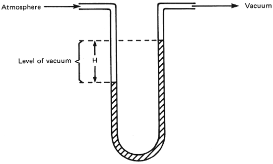
It can be measured as pressure difference with a mercury manometer in mm Hg (see diagram). The standard pressure is now kilopascals (kPa) with 100 kPa equal to the pressure difference between atmospheric pressure and absolute vacuum.
Vacuum is a pressure below atmospheric pressure, the term “negative pressure” is sometimes used but in milking machine terms it may be considered to mean “vacuum” measured on a scale in which atmospheric pressure at the time and place of measurement is zero vacuum.
Vacuum can be measured in a variety of units. A commonly used measure is the linear difference in height between two columns of mercury in a ‘U’ tube when one of the columns of mercury is subjected to a vacuum and the other open to atmosphere. (see diagram of ‘U’ tube). The difference in height of the levels is supported by atmospheric pressure.
In the past the most commonly used units have been inches, millimetres or centimetres of mercury (in Hg, mmHg or cmHg). Units now adopted by the International Standards Organisation (ISO) for International Standards of milking machines for vacuum measurement are kilopascals (kPa) with zero (0) kPa being equal to atmospheric pressure and 100 kPa absolute vacuum. Equivalent relationships for values of vacuum levels are:-
1 mmHg = 0.133 kPa
1 inHg = 3.386 kPa
Equivalents for vacuum levels of 50 kPa and 44 kPa that are the most commonly used levels for milking cows:
50 kPa = 14.8 inHg = 375 mmHg
44 kPa = 13.0 inHg = 330 mmHg
ACTION OF THE MILKING MACHINE IN EACH PULSATION CYCLE
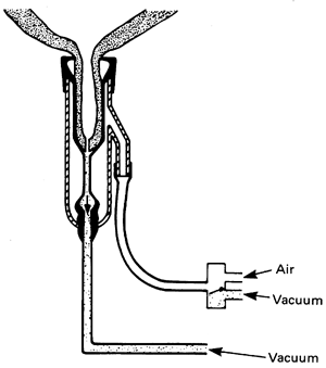
Pulsator connects pulsation chamber to vacuum, liner opens and milk flows.
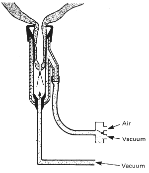
Pulsator connects pulsation chamber to atmosphere, liner collapses, squeezes the teat duct and prevents milk flow.
MILKING RATE
Milk flow from the teats increase with:
TEATCUP LINERS
Teatcup liners have important effects on milk flow and completion of milking.
The principles of machine milking were established many years ago and the basic method described below, is used in virtually all commercial milking machines although in a minority some modifications are made. The teatcup liner is the only equipment that comes into contact with the cows teats. The continuous vacuum within the liner causes the teat duct (streak canal) to open and the milk to flow because of the pressure difference between the milk in the teat and vacuum. To prevent damage or pain to the teat that would be caused by the continuous vacuum a system called pulsation is used. This makes the liners collapse on and below the teats about once each second massaging the teat and maintaining a more normal blood flow. In each pulsation cycle milk does not flow from the teat when the collapsed liner squeezes the teat duct.
Providing the cows ‘let down’ (ejection) has occurred the flow rate from the teat depends largely on the bore of the teat duct which is an inherent factor and not subject to management practices or training. Flow rates are also influenced by the mechanical properties of the milking machine. After the teat cups have been attached the flow rate reaches a maximum in about one minute, usually within the range of 2–5 kg/minute and the total milk flow period will range from 2 to about 8 minutes depending upon milk yield. Flow rates decline at the end of milking and when flow ceases there is usually a small amount of milk trapped in the sinus of the udder which can be removed by pulling ownwards on the clawpiece and massaging the udder (ie. machine stripping). With modern designs of liner the quantity of strippings is small (ie. less than 0.3 kg) and machine stripping is not usually practiced. The small amounts of milk that are left do not affect milk yield or the average chemical composition of the milk obtained or mastitis.
VACUUM FLUCTUATIONS
The fluctuations in vacuum in the teatcup liner have important effects on mastitis and milk flow. There are two types.
Irregular fluctuations
These occur when the teatcup liners slip or fall from the teats or air enters when milking units are changed carelessly. Vacuum recovery is slow if there is inadequate vacuum pump capacity.
Cyclic (regular) fluctuations
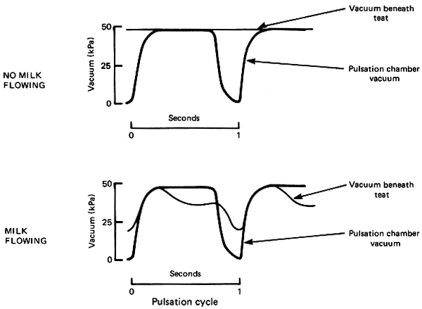
The cyclic movements of the liner in each pulsation cycle increase and decrease the volume of the liner under the teat. When milk is flowing this can cause marked changes in vacuum below the teat. This can be reduced by:
The main milking machine factor affecting milk flow rate is the liner vacuum. Raising vacuum levels gives faster milking but also increases strip yields and in practice a compromise level of about half atmospheric pressure is used (ie. 40–50 kPa, 300–375 mm/Hg). The pulsation characteristics also affect flow. An increased pulsation frequency (rate) gives faster milking but because this greatly increases the air admission in the machine and therefore the required pump capacity it is usual to keep pulsation rates at 50–60 cycles of liner opening and closing per minute. Because milk flow ceases in each pulsation cycle when the liner is collapsed on the teat, faster flow rates are obtained by using a wider pulsation ratio (ie. ratio of liner open time to liner collapsed time). For udder health reasons the ratios are usually not greater than 70:30. The design of the liner can also affect the flow rate but modern liners tend to have similar flow properties. Narrow bore (<24 mm) liners and those with low tension in the barrel (ie. not stretched in the teat cup) milk more slowly. The most important characteristic of the performance of a liner is the amount of strippings left at the end of milking which is mainly determined by the dimensions and hardness of the mouthpiece. Liner design is largely empirical and farmers determine the best liners for minimum strippings by trial and error.
Although the teat cup liners are connected to a pipeline maintained at a constant vacuum level there can be considerable vacuum fluctuations in the liners, mainly due to the movements of the liner wall brought about by pulsation. When the liner is opening and the milk is moving away from the teat along the short milk tubes the vacuum below the teat will increase markedly due to the increased volume of the liner and the kinetic energy of the milk in transit. These variations in vacuum occur with each pulsation cycle and are called ‘cyclic fluctuations’. The fluctuations are increased with adventitious air admission that occurs when liners slip on the teats or when machines are removed from adjacent cows udders (irregular fluctuations). These cyclic and irregular fluctuations generate impact forces which are important factors causing mastitis. Various methods have been used to reduce fluctuations to prevent them having deleterious effects. The most important are the provision of adequate airbleed holes in the claw or short milk tubes to aid milk flow and prevent flooding in the liner. Also useful has been an increase in the internal diameter of short milk tubes (eg. greater than 8 mm). These can be reduced by other modifications. In some designs the basic system of machine milking has also been modified to give lower levels of vacuum at the start and end of milking when there is no milk flow or by the inclusion of a positive pressure phase in each pulsation cycle to give increased let down stimulation.
VACUUM PUMP
| Most vacuum pumps are rotary oil sealed positive displacement pumps Air is drawn in through the inlet port by the rotation of the rotor, compressed and ejected to atmosphere. | 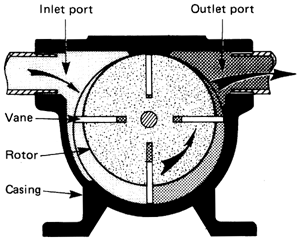 |
INTERCEPTOR
| A trap fitted in the main vacuum line to prevent liquid and dust being sucked into the vacuum pump | 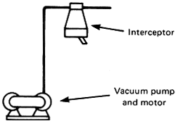 |
The function of the vacuum pump is to extract air from the pipeline system and in the majority of milking machines it is a rotary exhauster driven from either an electric motor or a stationary internal combustion engine, using pulleys and V-belts. This gives flexibility with speeds ranging from about 800–1500 rev/min and a corresponding ange of pump capacities to suit several sizes of milking machines. A few vacuum pumps are direct shaft coupled; their speed is then motor speed and cannot be changed. When operating with a vacuum at the pump inlet suitable for milking cows (50 kPa), the pumping capacity should be sufficient for the total number of milking units connected. This will range from 70 litres of air per minute per unit for installations with 20 units to 85 per litres per minute for the smaller plants with 5 units.* It will vary according to individual manufacturers design of equipment and the additional ancillary components included. Oil lubricated high speed vacuum pumps operate at speeds of between 850– 1440 revs/min. For each 0.75 kW (1 h.p.) of rated electric motor requirement the extraction capacity is approximately 280 litres of air/min. The pump should be fitted with drive belt guards, an effective silencer and, for oil lubricated pumps, an oil separator. Also, a nonreturn valve should be fitted in the exhaust pipe to prevent reverse rotation of the vacuum pump when switching off at the end of milking. This is to avoid debris from the silencer/exhaust pipe being sucked back into the pump. To prevent solid and liquid material being drawn into the pump from the milking installation, an interceptor/trap vessel with a capacity of not less than 15 litres is fitted in the main vacuum line adjacent to the pump, with provision for draining and cleaning. It should also have a float valve to shut off the vacuum in the event of it filling with liquid.
VACUUM REGULATOR
| An automatic valve to maintain a steady vacuum inspite of varying air usage. A preset force (weight or spring) holds the valve closed until vacuum lifts it and allows air to enter. Valve should maintain vacuum to within the limits of ±kPa of the designed working vacuum. | 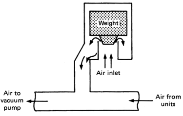 |
VACUUM GAUGE
| Indicates abnormal levels and fluctuations in vacuum, eg. serious air leaks, dirty regulator and slipping vacuum pump drive belts. | 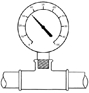 |
Vacuum regulator is an automatic valve fitted into the main vacuum pipeline near to the milking units that is designed to maintain the working vacuum level in the milking machine, despite the varying air usage during milking. It operates by admitting air into the pipeline when the vacuum increases above the predetermined level. The valve is held closed by a weight or spring until the vacuum in the system overcomes the closing force, allowing atmospheric pressure to open the valve. Weight operated regulators have a maximum capacity of approximately 550 to 700 litres/min. Spring operated regulators have capacities of up to 1400 litres/min. Servo or power operated regulators, which usually have remote sensing, utilize a small intermediate pilot valve to actuate the main air inlet valve. These regulators sense pressure changes in the vacuum pipeline at a position where more stable conditions might be expected to exist. They are readily adjustable with capacities varying from 1000 to 5000 litres of air/min.* A good regulator should be able to control the vacuum to within plus or minus 2 kPa of the working vacuum, be stable and not leak by more than 35 l/min, when nominally closed. All vacuum regulators have an air filter to filter the incoming air. The vacuum gauge indicates the vacuum in the pipeline system. Its most important function is to indicate abnormal levels and fluctuations in vacuum, eg. serious air leaks, dirty regulator and slipping vacuum pump drive belts. Universally the Bourdon type gauge is used. It should not be less than 75 mm in diameter, graduated at intervals of 2 kPa and be adjustable. Most gauges have dual graduations, kilopascals (kPa) and millimetres of mercury (mmHg), and have lines on the dial indicating the working vacuum level.
PULSATORS
Pulsators are valves that cause the liners to open and close on the teat once each second (ie. pulsation) by connecting the pulsation chamber of the teatcup to vacuum or atmosphere.
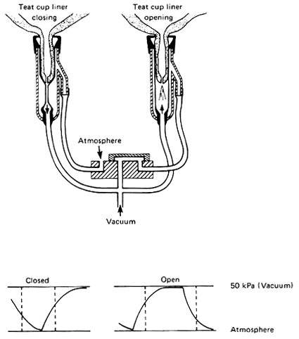
Pulsation chamber vacuum
The pulsator is a simple valve that alternately admits air and vacuum into the pulsation chamber formed between the rubber liner and he shell. This causes the liner to open and close during milking. The valve is activated either by a pneumatic (vacuum) or an electrical signal from a pulsator controller to give a frequency of 40–50 cycles per minute and a ratio (open to closed) of 1:1 to 2:1 (sometimes called 50:50 and 66:33). Relay pulsators are activated from a central pulsator controller, and self contained pulsators have built-in controllers. Most relay pulsators, electrical and pneumatic, pulsate the four liners of a cluster together (simultaneous pulsation). Self contained pulsators are better adapted to pulsating liners in pairs with two open and two closed (alternate pulsation). In the slide valve mechanism of self contained pulsators, the slide valve is arranged to produce a predetermined ratio. With a higher vacuum under the teat than in the pulsation chamber (sometimes due to milk flowing downhill) the liner will not open fully, slightly pinching the end of the teat, resulting in possible teatend damage. Conversely elevating the milk can reduce the vacuum under the teat, with the result that the liner does not fully collapse. This will influence the designed ratio of open to closed of the liner. These adverse conditions are minimised by ensuring that there is an air admission hole into the bowl of the claw to admit air within the range of 4–10 litres/min as recommended in milking machine standards. The pulsation rate of pneumatic pulsators is determined by a restriction in the air or oil damping system of the pulsator. With all pulsators, the size of the valve ports, length and bore of the pulse tubes determines the rate of extracting and admitting air. This determines whether a pulsator can operate more than one cluster and is a function of the basic design. There are however solid state electronic pulsators that control the rate and ratio which provide alternate pulsation and can operate two milking units. Air filters are fitted in the air intake to prevent dust getting into the alve mechanisms which should not be lubricated unless recommended in manufacturer's instructions.
MILKING CLUSTER
Consists of four teatcup assemblies each having a rubber liner and connected to vacuum by rubber tubes and claw. The air admission hole to stabilise the vacuum must be kept clear.
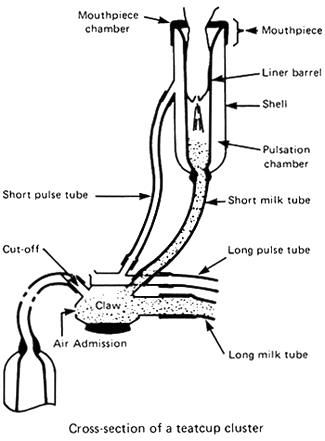
The cluster which attaches to the cow, consists of four teatcup assemblies (each having a shell, a rubber liner and a short milk and short pulse tube), a claw, a long milk tube and long pulse tube(s). Teatcup shells are normally made of stainless steel. Plastics or a combination of plastics and metal are also used. The liner is a flexible rubber sleeve having a mouthpiece, and when assembled in the shell under tension, forms an annular space (pulsation chamber) between the liner and shell. This pulsation chamber is connected to the pulsator through a nipple on the side of the shell via the claw. The teatcup assemblies are connected by short milk and short pulse tubes to the claw, which is connected to the milking and pulsation vacuum by a long milk tube and long pulse tube(s). To stabilise the vacuum in the teatcups during milking, the claw has a small air admission hole, about 0.8 mm in diameter, which admits approximately 7–8 litres of air/min into the bowl of the claw. This air helps to carry the milk away, preventing flooding and violent vacuum fluctuations. The claw is made of stainless steel or a combination of plastics and stainless steel, and usually weighs about 0.5 kg and the total all up weight of a milking cluster is about 2.5 kg. The weight of a milking cluster is important and the correct weight relates to the design of liners. Too little weight gives incomplete milking because of high levels of strippings, too much weight will result in milking units falling off during milking.
The bore of the rubber short milk tubes should not be less than 8 mm and the short pulse tubes not less than 5 mm, and the long milk tube should not be less than 12.5 mm. The effective claw bowl volume should not be less than 80 ml.
MILK AND AIR SEPARATION
There are several methods of extracting milk from the vacuum system of pipeline milking machines.
| The milk is collected in a receiver where the milk and air are separated ready to be extracted with: | |
| a) a centrifugal releaser milk pump | 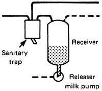 |
| b) double chamber releasers with weight or float operated mechanical valves and the New Zealand pulsator operated ‘spit chamber’ releaser | 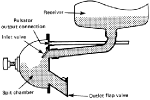 |
direct connection to a refrigerated farm vat (bulk tank) that is designed to operate under vacuum eliminating the need for a conventional receiver releaser.
In pipeline milking installations it is necessary to include a method of extracting milk from the vacuum system. A receiver vessel is fitted to act as a milk reservoir and air separator and from this the milk is pumped out. It is made of either glass or stainless steel and may have a capacity of 35 to 160 litres or more depending on the method of cooling and storing the milk. During milking the weight or level of milk in the receiver is used to start the milk pump (releaser). Releaser milk pumps for extracting milk out of the vacuum system are: centrifugal, with capacities of at least 4550 litres per hour, or diaphragm, with capacities of approximately 2000 litres/hr for a single ended pump. Other methods for extracting milk from a vacuum system are double chambered releasers with weight operated mechanical valves and the ‘spit chamber’ releaser. These do not require electricity and the latter utilises a pulsating vacuum to alternately open and close flap valves allowing the milk to drain out of the second chamber.
In addition to the interceptor for the vacuum pump, a sanitary trap, is fitted in the vacuum pipeline adjacent to the receiver. This is a glass vessel of not less than 3 litres capacity that separates the part of the milking machine through which milk passes from the air system, preventing movement of liquid from one to the other. If milk enters the sanitary trap it is an indication of a fault in the machine. Therefore, it should be mounted within sight of the milker and be fitted with a float ball to shut off the vacuum. The vacuum connection between the sanitary trap and the receiver should slope away from the receiver to the sanitary trap.
RECORDING AND SAMPLING MILK
To measure the yield of each cow requires:-
| a) the milk to be collected in a calibrated glass recorder jar. | 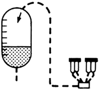 |
| b) the milk to pass through a meter which can either take a constant proportion sample or to measure the whole yield in discrete batches and totalled. | 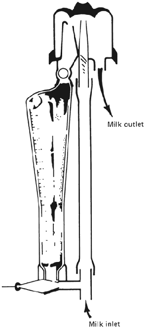 |
All methods have provision for taking a representative sample of the total yield for milk quality (fat, protein and lactose) analysis.
In pipeline recorder milking installations, milk flows directly from the cluster into a rigidly mounted calibrated glass recorder jar where the milk is intercepted and held to allow measurement of the total individual cows milk yield. This is done by using either the calibrations etched on the side of the glass jar or the weight of the contents for jars that are supported on electrical strain beams.
In direct to pipeline milking machines not fitted with recorder jars, milk yields are measured with milk meters. There are several designs of meters. Basically there are two distinct methods used. (1) Proportional flow; these collect a constant proportion (about 2.5% ) of the milk flow into a calibrated flask the contents of which are recorded manually or electrically. (2) Batch; the total flow of milk is continuously measured in discrete batches and the aggregate of the batches recorded.
Proportional flow meters used for manual recording are relatively simple and inexpensive. Electrical recording of milk yields, depending on complexity can be costly and are usually linked with electronic management data recording systems.
All these methods of milk recording have the facility for collecting a milk sample for chemical analysis and are required to be within set limits of accuracy for yield and ability to collect a true representative sample of the milk. These limits are laid down in an International Standard for milk yield recording equipment by I.C.R.P.M.A.*
* International Committee for Recording the Productivity of Milk Animals
MISCELLANEOUS EQUIPMENT
Milk flow detection
Devices are fitted to assist the milker to determine the end of milk flow.
These can be:
sight glasses or ‘windows’ in the claw or tubes
glass recorder jars
flow indicators which show visually when the flow rate falls below a definite level
electronic equipment that measures change in flow rate
Mastitis detectors
| - filters' in a transparent holder which indicate the abnormal milk |  |
Teatcup liner ‘shields’
| These are fitted in the teatcup liners to reduce mastitis by preventing contaminated milk droplets impacting the teat ends when the vacuum fluctuates in the liner. | 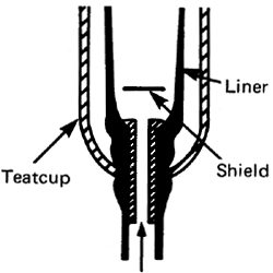 |
‘One-way valves’ (Non-return)
| These are fitted in the claw, in the short milk tube or in the teatcup liner to reduce mastitis by preventing reverse-flow of milk |  |
With all milking units, except those using transparent recorder jars, there is some provision made for observing milk flow. This can be a metal claw fitted with “windows”, or a claw made in a transparent material or, a short length of clear tubing fitted in the long milk tube. Observing flow in these ways can be misleading and there are now milk flow indicator devices that work on the basis of milk flowing into a small container with a submerged metering orifice for maintaining a milk level. Variations in this level can be observed or detected electrically, using a magnetic float switch or electric probes.
In modern large milking installations, milk flow detectors are used to sense the end of milk flow (less than 250 g/min) and activate automatic cluster removal (A.C.R.) equipment. This equipment prevents overmilking and enables the operator to use more units by reducing the workload. It eliminates waiting to observe when an animal has finished milking and manually detaching the cluster. Electrically operated milk yield recording equipment eg. glass recorder jars on strain beams and milk meters can be used as flow detectors and linked to A.C.R. equipment. In this way the milking cluster is removed when flow rate has fallen below a predetermined level. A useful device that can be fitted in the long milk tube is a small in line filter used as a mastitis detector. It retains milk clots enabling clinical mastitis to be detected and also acts as a coarse filter for removing extraneous material which is an advantage when using flow detectors or milk meters that have small metering orifices etc. The filter screen is easily removed for rinsing off the clots after each cow and the detector is cleaned in situ by the normal cleaning system of the milking machine.
To reduce or eliminate the effect of vacuum fluctuations that occur during milking “shields” can be fitted in the bottom of the liners near the outlet preventing contaminated milk returning up the short milk tube from impinging on the teat end. The shield consists of a disc of stainless steel or plastics of a diameter that leaves a space etween the edge of the disc and the liner wall not less than the internal diameter of the milk outlet. A more positive method to prevent the reverse flow in a conventional cluster is to fit non-return valves in the claw or short milk tubes together with a small air admission hole between the liner and the valve to maintain normal milk flow. A system of milking with non-return valves but without the air admission holes has been investigated and preliminary results show the development could have advantages.
WATER HEATERS
The quantity of hot water required depends on the size of milking machine and the cleaning methods used. It is essential to have an adequate supply. The methods of heating can be, a solid fuel or oil fired boiler, an open top un-insulated electrical wash boiler or a self contained insulated electric water heater. Complete with time switch, thermostat and automatic water filling.
The electrical heating element should be fitted with a clear space beneath it for the hard water scale that will collect.

For nearly all milking machine cleaning methods an adequate supply of hot water is necessary. Water heaters vary from simple free standing insulated or uninsulated tanks filled with a hose and manual control to insulated tanks automatically filled and heated at predetermined times.
The water capacity required is dependant on the washing system used (hand or in-place cleaning) and the number of units to be washed. For in-place cleaning the amount of water required for each milking unit will be 12 literes of water at 85°C for recirculation cleaning and 18 litres at 96°C for a single pass “boiling water” cleaning system. Additional hot/warm water may be required for udder washing and calf feeding. Whatever cleaning methods are used the water heater should be capable of producing near boiling water for the purpose of giving the installation a periodic heat treatment. The temperature of the wash solution in closed pipe work is affected by the vapour pressure of the liquid. Water at normal atmospheric pressure at sea level boils at 100°C (212°F) and at a vacuum of 50 kPa (14.8 inHg) it boils at 81.7°C (179°F). Thus when cleaning pipeline milking machines with water solutions under vacuum, the maximum temperature which can be obtained ill depend on the operating vacuum level in the installation, ie., the higher the vacuum level the lower will be the temperature that can be obtained. For similar reasons, at an altitude of a 1,000 metres where atmospheric pressure is reduced to about 89 kPa (12.9 lb/in2), water in an open vessel will boil at the lower temperature of 96°C (205°F) instead of 100°C (212°F) at sea level.
Although any fuel can be used for water heating the most commonly used is electricity for cleanliness and convenience. In areas with hard water supplies, a hard scale will build up in the tank and on the heating element. The electrical heating element should be fitted with a clear space beneath it (approx. 10 cm) and be of a type that will flex during heating and cooling, breaking off the hard water deposits that will fall into the space below. Provision should be made for easy removal of this accumulated scale.
For economy any water heater should be well insulated, fitted with a thermostat and preferably a time switch. In soft water areas tanks that are manufactured in galvanized sheet metal are not suitable and copper should be used.
MAINTENANCE
For effective milking giving good yields of high quality milk, fast milk removal and to minimise mastitis, good milking machine maintenance is required. Maintenance routines should be provided by the manufacturers of the equipment.
These will include
FAULTS FOUND MUST BE CORRECTED
Otherwise the checks are of no value.
The basic layout and operation of milking machines is normally straight-forward and similar for all standard milking machines. However, it is important that a correct maintenance routine is followed. Faulty milking machines can result in poor milk let down, slow milking, milk of high bacterial count and mastitis. Maintenance is a responsibility of the person regularly using the equipment with simple checks made at each milking and more detailed ones at weekly or less frequent intervals.
The maintenance instructions described deal with the essential routines and do not include checks on the many optional items not fitted in large modern parlours, (eg. automatic cluster removers, milk meters). These vary considerably and the maintenance procedure should be obtained from the supplier. Because the overall performance can be assessed only with special measuring equipment a fullscale test should be carried out by the manufacturer, installer or extension service at least once per year.
The following routines should be read in conjunction with maintenance procedures provided by the suppliers of the milking equipment.
MAINTENANCE CHECKS
At each milking
| - check pipelines and interceptor are free from milk or water, if found, drain and flush with chlorinated water (100 ppm) |  |
| - check for water behind teatcup liners if found drain | 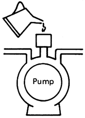 |
| check oil level in pump, if necessary top-up to correct level | |
| - check vacuum level and rate of recovery, if level too high check vacuum regulator, if recovery is slower than usual to reach working level, look for leaks into machine | 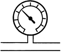 |
| - during milking listen to ensure that regulator is continuously letting air into the vacuum system | 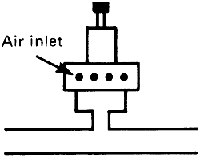 |
| - check air admission hole in claw is clear | 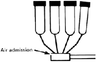 |
Confirm that wash water is not retained in milking machine pipelines, particularly the milk lines. This water is likely to have a high bacterial count and reduce the quality of the milk. If water is found drain and flush the milk lines with hypochlorite solution (100 ppm) before milking. In most countries it is an offence to add water to milk and residual water in a milking machine may be sufficient to fail the freezing point of milk test. With some machines and washing systems water can enter the pulsation chambers of the teatcup, damage pulsators, affect the pulsation of the liner and gain entry into the main vacuum systems giving high levels of bacterial contamination. Check the clusters for split liners.
Before starting the vacuum pump confirm that the interceptor is empty either by opening the drain valve or detach the trap for inspection.
Confirm that the oil level in the vacuum pump oiler is at a satisfactory level, ie., not less than half the capacity of the oil reservoir.
Observe the vacuum gauge, the working level should be reached within five seconds, or consistant with the time stated by the manufacturer when the equipment was installed. If there is a delay bove that expected, check for air leaks at open stall or drain cocks, a misplaced receiver or bucket lids and where a centrifugal milk pump is used, for failure of the non-return flap valve to close. If all these items are in order check that the vacuum pump drive belts are not slipping. The working vacuum should be constant and the reading on the vacuum gauge should be the same before and after putting the milking clusters on the cows. Faults found should be corrected at the earliest opportunity.
MAINTENANCE CHECKS
At each milking (continued)
| - listen to ensure normal sound from pulsators. Check suspect action with thumbs in teatcup liners | 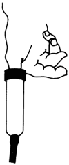 |
| After each milking | 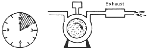 |
| - allow pump to run for 10 minutes after end of milking | |
| - check for milk in interceptor. If found find cause and wash out pipeline and interceptor with a warm detergent solution. | 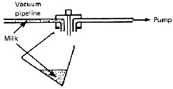 |
When all units are in operation and the working vacuum is correct, listen to the vacuum regulator. If there is no sound of air entering the regulator, a serious shortage of pump capacity is indicated. If on starting the vacuum pump the vacuum level rises first to a high level then drops to the working vacuum level the regulator is sticking and requires cleaning.
Check operation of the pulsators. The sound from the pulsators should be regular. When noise is abnormal look for damaged/split rubber pulse tubes particularly at the nipples on the claw, or faulty pulsators. If there is any abnormality check pulsation of liners with thumbs (see Weekly Check).
Examine the milking cluster for damaged rubberware, particularly the short milk and air tubes at the claw nipples.
Condensation or moisture from milking or plant cleaning can collect in the vacuum pump. This rusts the pump body producing, a condition which reduces performance and ultimately would require pump eplacement. This can be avoided by allowing the pump to run for approximately 10 minutes after milking to exhaust the moisture and dry out.
After switching off the vacuum pump examine the interceptor. If milk is found in the interceptor, this may indicate a split liner or malfunctioning of the milk pump. Find the cause, wash out vacuum line and interceptor.
MAINTENANCE CHECKS
Weekly
| - check pulsator action of all clusters with thumbs in teatcup liners | 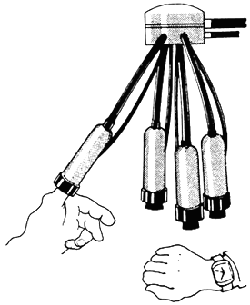 |
| a) for pulsation ratio of squeeze to release | |
| for number of pulsations per minute |
Inspect all rubber tubes for kinking, flattening or damage, in particular short pulse tubes and milk tubes for holes, replace if necessary.
To test the pulsation and liner wall movement use the thumbs to sense the movement of the teatcup liner walls. This is done by inserting the thumbs into diagonal pairs of teatcups in turn with the others hanging in the cut-off position; the controls being set for milking. To make certain that the pair of teatcups not being checked are sealed they can be closed with rubber plugs (bungs). With experience abnormal action of the liner is readily detected. If the liners open and close completely and the action of the machine is not painful it will normally be satisfactory for milking. Failure to collapse indicates that the air inlet to the pulsator is blocked or that the pulsator valve is not working properly and the pulsator must be replaced. If this is discovered the operator will find that the cows are uncomfortable and restless and kick clusters off. The ratio of the liner open to closed cannot be confirmed by this test but it should be possible to detect that the collapse or closed phase is shorter than the open, milking phase. If the pulsation appears to be unsatisfactory check for damaged short and long air tubes.
When checking the liner wall movement confirm that the speed of pulsation is correct. Slow pulsation will give longer milking times. In self-contained individual pnuematic pulsators this slow action is usually due to a low vacuum level or a dirty slide valve. Some designs f pulsators have a speed adjustment facility, this should be reset if incorrect. Most designs of pulsators are designed to operate in the range of 50–60 pulsations per minute. The pulsation speed can also be checked during milking by a slight pressure on a short pulse tube with thumb and fore finger.
| - a slack vacuum pump drive belt will result in wear and loss of vacuum. Check tension by deflecting belt, movement should not exceed 15 mm (0.6 in). Also check oil level in vacuum pump oil reservoir and refill. |  |
| - inspect air filters on pulsators and vacuum regulators. Clean off light dust deposits by brushing or blowing. Heavily contaminated foam plastic filters should either be renewed or washed in warm detergent solution. |  |
VACUUM PUMP DRIVE BELT AND OIL LEVEL OF PUMP
Check the Vee drive belt tension on vacuum pumps. Deflect the belt downwards at a point midway between the pulleys. The movement or deflection possible from the rest position should not exceed 15 mm (0.6 in). A slack drive belt will slip, reducing the vacuum pump performance. If serious belt slip is occuring there will be visible particles worn from the belts on the floor. If adjustment is needed care should be taken to keep the pulleys in alignment. Check the oil level in oil reservoir and if necessary refill.
FILTERS
Air filters on pulsators and vacuum regulator must be kept clean. The frequency of cleaning depends on whether they are operating in a clean or dusty environment. Most modern components are fitted with foam plastics air filters or screens. Brushing or blowing will remove light dust deposits. Heavily contaminated foam plastics filters should either be renewed or washed in a warm detergent solution and thoroughly dried before re-assembling into the pulsator.
Monthly
| -dismantle and clean weight
operated vacuum regulators.
Using a soft brush and a
solvent, methylated spirit.
Taking care not to damage
valve surfaces. Remote sensing regulators |  |
| - follow manufacturers instructions. | |
| - wash out vacuum line and interceptor, using hot detergent solution and drain. At the same time check interceptor for leaks, from rubber seals or small holes in base. | 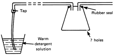 |
Dismantle weight operated vacuum regulators, clean valve face and valve seat with a solvent (methylated spirit). Care must be taken to avoid amage to valve surfaces. Remove difficult deposits with metal polish. Clean regulator filter before the regulator is reassembled and ensure that the weight is evenly balanced.
Servo or power operated remote sensing designs of regulators should be serviced according to the manufacturers instructions as correct reassembly is not always easy. They will require the conical valve face to be cleaned and rubber diaphragm(s), if applicable, inspected. DO NOT oil valve or valve guides.
Check that damping rings or rubbers etc are not damaged.
Particular care must be taken when reassembling Servo Regulators. Observe closely during dismantling how rubber diaphragms, pilot valves etc, are fitted, so that they can be assembled correctly.
The vacuum line and vacuum pump interceptor trap should be washed through with hot detergent-hypochlorite solution. Make up a wash solution of detergent in hot water (10–12 litres at 60–70°C) With the addition of hypochlorite (250 ppm). In the case of branched lines, this quantity should be drawn in along each branch. Provision should be made to enable this to be carried out easily by providing at the end of each pipeline a cock or valve with a nipple suitable for attaching a rubber tube to suck the liquid from a bucket into the pipeline. When sucking the solution into the pipeline, allow air to be drawn in at the same time by withdrawing the tube from the solution at frequent intervals. The air liquid mixture will achieve a scrubbing action in the pipeline and be more effective than a solid stream of liquid. Most interceptor vessels are about 18–20 litres capacity and must be emptied after each 12 litres of cleaning solution has been drawn into the plant. After washing the lines the drain cocks must be left open to allow the vacuum system to drain. Before re-installing the interceptor, check the rubber eals and observe if there are any small holes in the base of the interceptor where air leaks can occur. These can cause a carry over of liquid from the interceptor to the detriment of the vacuum pump.
carry out manufacturers maintenance instructions for PULSATORS Pneumatic self contained pulsators, if badly worn, can usually be made good by replacing worn components, ie. rubber diaphragms, valve slide and spring. Exchange reconditioned pulsators are available.
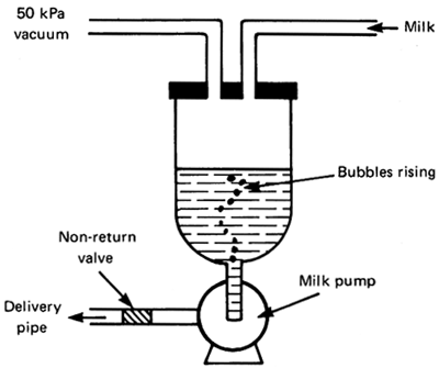
check for air leaks at MILK PUMP rubber non-return valve or shaft seals. With water in the receiver jar and under vacuum look for air bubbles in jar. If present dismantle and find cause.
Pulsator maintenance varies depending on type, (electronic, electro-pneumatic and pneumatic) and whether relay or self contained. Manufacturers instructions should be followed. Filters, air inlet ports and in the case of pneumatic pulsators, the valve and valve slides require cleaning.
A pulsator performs about 6 million operations a year and is therefore subject to considerable wear. A badly worn pulsator can usually be made to operate satisfactorily by replacing the worn components with new parts supplied by the manufacturer e.g. rubber diaphragms, valve slides and springs. It will normally be necessary after two or three years to replace pneumatic pulsators and pneumatic relays. Manufacturers may have an exchange service providing reconditioned pulsators.
MILK PUMPS
The performance of a centrifugal milk pump can be seriously affected, even made inoperative, by air leaks at the rubber seal on the drive shaft or the non-return flap valve fitted in the pump outlet or delivery pipe. Where glass receivers are in use, test for leaks by putting approximately 4 litres of water in the receiver with the milk pump not working. With the receiver vessel under vacuum look for air bubbles rising to the surface from the receiver outlet. If a continuous stream of bubbles is seen dismantle the non-return valve and examine rubber flap for wear and distortion, renew if necessary. If leaks continue replace pump or dismantle and renew shaft seal, inspecting shaft for wear. It will be necessary to replace pump if there are signs of annular grooves on shaft.
Routine replacements
Yearly
A full test of the milking machine must be carried out once a year by an experienced technician as laid down in the International Standards; ISO 5707 “Milking Machine Installations - Construction and Performance” and ISO 6690 “Milking Machine Installations - Mechanical Tests”.
Carry out any remedial work recommended.
Further Reading
Machine Milking, Technical Bulletin 1. The National Institute for Research in Dairying, Reading, England. Reprinted 1983.
A full test of the milking machine must be carried out once a year by an experienced technician as laid down in the International Standards; ISO 5707 “Milking Machine Installations - Construction and Performance” and ISO 6690 “Milking Machine Installations - Mechanical tests”.
Carry out any remedial work that the tests indicate are required.
RUBBERWARE, PARTICULARLY LINERS, SHOULD BE REPLACED WHENEVER IT BECOMES MISSHAPEN OR DAMAGED. LINER LIFE DEPENDS ON THE NUMBER OF COWS MILKED BUT IT IS SUGGESTED THAT LINERS SHOULD BE RENEWED AT LEAST TWICE A YEAR AND OTHER RUBBER PARTS ANNUALLY
INTERNATIONAL STANDARDS FOR MACHINE MILKING INSTALLATIONS AND TESTING (ISO 5707 and 6690, 1983-02-01)
In recent years the International Standards Organisation (ISO) a world federation of national standards institutes (ISO member bodies) has worked with other organisations for a standardisation of the terms and descriptions of the components used in machine milking and an acceptable performance of milking machine installations. It has drawn on recent research and devised a standard unifying the many national standards that existed. Furthermore a test procedure has been produced which can be used to assess the acceptability of milking machine systems and to check their performance at regular intervals after installation.
The International Standard, 5707, on Milking Machine Installations was prepared jointly with the International Dairy Federation (I.D.F.) and other interested bodies, ie., European Committee of Associations of Manufacturers of Agricultural Machinery (C.E.M.A.) and the International Committee on Recording the Productivity of Milk Animals (I.C.R.P.M.A.). It specifies the minimum performance requirements and certain dimensional requirements for the satisfactory functioning of milking machines. In addition it lists the requirements of materials, construction and installation. ISO Standard No. 6690 on Mechanical tests was produced at the same time with the object of providing test procedures for confirming that an installation meets the minimum requirements of ISO 5707.
The following is a brief outline of items covered by the standards.
Vacuum pumps should be of adequate capacity to meet the operating requirements for both milking and cleaning and to provide a reserve. The reserve capacity is calculated for each milking installation. A formulae is given for calculating this, together with a formulae to calculate the effect of altitude on vacuum pump capacity. The installation of a separate vacuum system is recommended for ancillary vacuum-operated equipment. However, where this is not provided, an additional allowance for vacuum-operated equipment that does not operate during the static tests should be added to the effective reserve figure. Manufacturers are required to show the air consumption on all components. There are recommendations for the installations of vacuum pumps and exhaust systems. Facilities for measuring vacuum and air flows should be provided.
Vacuum regulators should be capable of controlling the vacuum pump used. They should be marked with the designed working vacuum level and with the air flow capacity at this level. A sensitivity standard has een introduced, together with standards for regulator leakage.
The acceptable drop in vacuum due to friction within the air pipeline (milking vacuum) is stated and recommended diameters of internal pipes are given for various air flow rates.
The interceptor capacity should be at least 15 litres. It should also be provided with an automatic cut-off and drainage facilitie. The inlet to and outlet from the interceptor should be the same diameter as the air pipeline.
A sanitary trap should be fitted to form a connexion between the vacuum system and the receiver vessel.
Requirements for pulsation ratio are closely defined, specifying minimum ‘collapse’ and ‘open’ phases of the pulsation cycle.
Where milking pipeline systems are installed, a specific recommendation has been made for pipeline sizes to ensure that the vacuum drop does not exceed 3 kPa with all units working. The diameter is determined in relation to the total length of the line and the rate of milk and air flows. No risers are permitted.
Where recorder jars are used, the design should be suitable for in-place cleaning and recommendations are made in relation to the height of installation (ie. metres above sea level)
To avoid any unnecessary vacuum drop in the milking system, attachments installed between a cluster and the milking pipeline (eg, recorder jar or bucket) should not cause a vacuum drop of more than 3 kPa at a milk flowrate of 3 kg per minute.
Detailed specifications and minimum internal dimensions are given for flexible tubes, ie, long milk tubes, 12.5 mm; short milk tubes, 8 mm; long pulse tubes, 7 mm except for bucket milking with alternate pulsation which is 6 mm; short pulse tubes, 5 mm and vacuum tubes 10 mm. There are also requirements for teat cup liners, shells and claws.
The standard also requires the installer to provide written instructions for operating and cleaning the equipment and also mechanical details of the system.
Briefly this is done by first observing that the correct pipe sizes and method of installing and construction are used. Then with the mouthpiece of the liners sealed with bungs, the vacuum pump running and all components operating, confirm that the vacuum pump capacity is sufficient to give the effective reserve required to the size of installation. This is done by measuring the air flow and vacuum level with an air flow meter and vacuum gauge. Next a check is made that the regulated/controlled vacuum level is correct and stable. Then with a continuous vacuum recording instrument connected to the pulsation chamber of a teat cup assembly, record the pulsation characteristics and confirm that the results for each unit is satisfactory.
These results should be entered on a standard form and compared with the original test results. The installer of the installation should carry out the commissioning test with the records left on the farm for future comparisons.