![]()
![]()
![]()
5.1 Rationale for construction of large diameter wells
5.2 Dimensions for large diameter wells
5.3 Excavation
5.4 Lining the excavation
5.5 Equipment for raising and lowering materials
5.6 Moulds
5.7 Concrete work
5.8 Safety
5.9 Finishing large diameter wells
As pointed out in Table 1, large diameter wells have some inherent disadvantages when compared with small diameter wells, including:
- greater effort and longer construction time
- greater safety hazards during and after construction
- difficulty in preventing contamination
- generally lower rate of inflow for the effort involved.
There are circumstances, however, which make the construction of large diameter wells necessary:
i. inability to obtain or maintain pumps or special buckets necessary for small diameter wellsii. desire to use some type of water raising system requiring more space than is available in a small diameter well (e.g. continuous chain and buckets)
iii. desire to improve or repair existing large diameter wells. iv. necessity of storing water where the aquifer is of extremely low permeability v. low cost labour is available
vi. local skills are available.
Large diameter wells are almost invariably circular in horizontal cross-section. This configuration (i) makes the sides most stable during excavation; (ii) uses the least lining material for a given cross-sectional area; and (iii) makes the best use of the compressive strength of masonry linings. One possible exception might be wells in which horizontal timber cribbing is used as a lining. In this case, the horizontal cross-section would be rectangular, preferably square.
The inside diameter of hand dug wells normally ranges between one and two metres. At the lower limit the small size of the excavation tends to impede work, since there must be space for at least one worker, his tools and the bucket into which he is loading the excavated material. Furthermore, after the water table is reached, a cylindrical caisson is normally lowered inside the original shaft, thus reducing work space even more.
As the diameter is increased, certain practical limits are reached, however, since the volume of excavated material is proportional to the square of the diameter and the volume of material necessary to line the excavation is roughly proportional to the diameter. For example, the volume of material excavated from a two metre diameter well would be four times that excavated from a one meter diameter well. As a consequence, the vast majority of dug wells are found to have diameters in the range of 1.2 to 1. 5 metres (4 to 5 feet). The larger size allows as many as four large well buckets to be used simultaneously if raising pulleys are properly located.
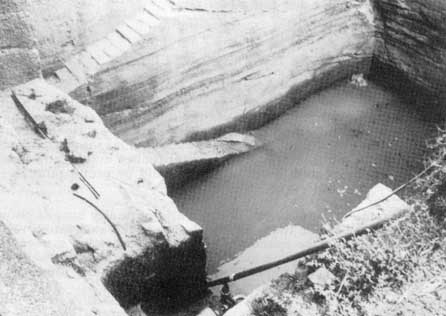
Extremely large diameter excavations serving a dual cistern-well function do exist (Figure 43). Some have stairs built into the sides allowing people to descend to the water level to dip out water. The stairs are normally used mostly during construction and maintenance, however. The construction of such structures could not be recommended, except in very special cases, due to the great effort of construction. It is obviously inefficient to lower and raise the entire body weight of the water carrier to the ground surface from the water table. Just raising the water is most efficient.
The major goal and challenge of excavation is accuracy, both locational and dimensional, i.e. the centreline or axis of the excavation must be maintained as absolutely vertical as possible while maintaining the radius of the excavation as exactly as possible about the axis. Vertical accuracy is necessary to prevent angular and offset errors between successive sections of the lining. Radial accuracy is necessary, because the excavation acts as the exterior mould for the lining. Where the radius of the excavation is too small, a thin, weak spot in the lining will occur. Where the radius is too large, a thick spot, wasteful of material will occur.
The location of the axis can be determined easily and accurately at any time or depth by means of a plumb line. The line may be attached to a special gauge stick with a hole near each end which lies along a diameter of the well at the ground surface and indexes over two steel rods securely driven into the ground on either side of the well (Figure 44a). If this stick is used to determine the centre of the well at the outset, it and the plumb line will serve to define the well axis anytime it is indexed over the two steel locating pegs. If there is danger of these pegs being knocked askew during the construction process, they should be set in concrete.
Hand tools, in local use, are normally adequate for carrying out the excavation. These might include spades, bars, picks and mattocks. Sometimes handles are shortened for use in the confined space. The hole is then excavated somewhat under size to the desired depth keeping the bottom reasonably level. Excavated material is placed in a bucket or basket by the worker(s) doing the digging and is raised to the surface by rope and pulley by other workers who dump it some distance from the well. This distance should be great enough to prevent the pile of excavated material from becoming an obstacle, and to prevent it from being washed back into the well by rain.
After rough excavation, the hole is accurately trimmed to its finished dimension. This necessitates use of the plumb line. One method consists of accurately driving a pointed metal rod into the centre of the excavation as determined by the plumb bob, and then checking the top of the rod with the plumb bob to assure that it is vertical. The top of the rod should be at least as high as the highest point to be trimmed. Once placed, the rod can be used as a temporary axis. A gauge stick can then be used to check the radius of the excavation as trimming proceeds. Alternatively, a small scraper or mattock attached to a chain of correct length pivoted around the axis rod can be used for final trimming. Another method uses a cross whose legs are just slightly shorter than the desired diameter of the excavation. This cross is suspended from the plumb line by means of an eye at its midpoint so that its legs are both in the horizontal plane. Four vertical grooves are carefully cut in the walls of the excavation to just allow the cross to hang freely. Trimming then proceeds until the cross has the desired clearance at any position when suspended from the plumb line. The bottom of the excavation should then be carefully levelled if a mould is to be placed for lining the excavation.
Lining the excavation serves at least three purposes:
i. It protects the workers against cave-in during construction.ii. It stabilizes the sides of the well preventing sloughing off and washing in of material during use, thus extending the life of the well.
iii. It can prevent the entry of surface water and resulting contamination where the water is for human consumption.
Three different systems of lining are in general use (Table 3). More than one system may be used in a given well depending on the conditions encountered. Several different types of lining may be used with each system.
System I (Table 3, Figure 44) consists of excavating and accurately trimming one metre of depth. A horizontal annular groove is added near the bottom of the excavation which is then lined. Another metre of depth is then excavated, trimmed and grooved which completely undermines the lining of the first metre. This lining is supported, however, by being keyed into the annular groove. Additional support may be obtained by driving short lengths of reinforcing rod radially outward into the sides of the excavation with ends protruding into the excavation prior to placing the lining. As soon as the second metre has been prepared, it is likewise lined. Alternate excavating and lining continue downward until the water table is reached. At this point another method is necessary, since the presence of water and the usual instability of the saturated material make this method unworkable.
The most common method of lining is to pour concrete into the annular space between the excavation and a cylindrical mould. Thickness of lining varies from 5 to 15 cm with dimensions about midway between the two extremes being most common. In general, the thinner the lining the more skill and care required to get an adequate result. Prior to pouring, it is important that the mould be levelled and carefully centered using the plumb line. The mould is designed so that it can be collapsed or disassembled for removal after the lining has gained sufficient strength. After the first metre, the depth of each subsequent excavation is made between five and ten centimetres greater than the height of the mould. This leaves a space between the top of the mould and the bottom of the previously cast lining through which concrete can be placed behind the mould. This space must subsequently be trowelled full of concrete. While one metre per day could theoretically be excavated and lined, this is difficult to achieve consistently, especially at greater depths.
It is important that there be continuity between successive pourings. This can be ensured by driving lengths of reinforcing rod vertically downward into the bottom of the excavation around its periphery where the lining will be placed. When the lining is poured the upper halves of the rods become part of it. The lower halves of the rods are exposed during the subsequent excavation and become part of the next section of lining. These rods provide continuity between adjacent sections of lining.
Where moulds are unavailable, a fairly fine mesh of vertical and annular reinforcing rod can be set up around the periphery of the trimmed excavation. Concrete mortar is then trowelled into the reinforcing mesh and smoothed without the aid of a mould. This method requires more man-hours, more skill and more reinforcing rod than the previous method, however, a good mason can achieve a satisfactory result.
An alternative method uses brick or stone as a lining material. It is necessary to pour a reinforced concrete sill or ring at the bottom of each level of excavation on which to lay the brick or stone lining. This ring must extend well into an annular groove around the bottom of the excavation, so that it will support the lining above it after it is undermined.
This method minimizes the quantity of concrete, reinforcing rod and mould needed, but it increases the man-hours and skill required. It is also difficult to seal out surface water with this kind of lining.
Some efforts are being made to manufacture fibreglass half rings which can be easily installed instead of using concrete. So far the fibreglass appears to be rather costly and certainly requires sophisticated manufacturing techniques not often available where self-help wells are needed.
Fig. 44 Excavating and lining large diameter well. (a) excavate and trim first metre including support groove

Fig. 44 Excavating and lining large diameter well. (b) drive reinforcing rod into sides and bottom of excavation, place mould and pour concrete

Fig. 44 Excavating and lining large diameter well. (c) remove mould and excavate and trim next metre of depth

Fig. 44 Excavating and lining large diameter well. (d) drive reinforcing rod into sides and bottom of excavation, place mould and pour concrete

SYSTEM I : ALTERNATELY DEEPEN AND LINE SHAFT
(approximately one metre depth is excavated and lined before repeating the process)
|
General limitations and capabilities of technique |
Type of lining |
A. Reinforced concrete cast in place |
B. Concrete trowelled into reinforcing rod grid |
C. Brick or stone on. concrete 'footing' anchored into sides of excavation |
|
Applicable above water table only, since absence of water and stability of excavation are required. Must be used in conjunction with caisson method below to finish well. Depth virtually unlimited. |
1. Description |
Concrete is cast in annular space formed between sides of excavation and collapsible mould |
A reasonably fine grid of vertical and annular reinforcing rod is placed around outside the excavation. Concrete mortar is trowelled into grid and smoothed without a mould. |
An annular reinforced concrete ring is poured at bottom of excavation. T his ring is keyed into a groove around outside of excavation and supports masonry lining laid on it. |
|
2. Requirements |
Collapsible mould, reinforcing rod, concrete. Annular groove is cut around outside of excavation to support lining when it is subsequently undermined for further deepening. |
Reinforcing rod, concrete, skilled mason. Annular grooves and/or rod driven radially into sides of excavation may be used for support during undermining. |
Small mould for concrete ring, reinforcing rod, concrete, brick or stone. |
|
|
3. Advantages |
Smooth, strong, uniform lining. Most commonly used method. High skill not required. |
No mould required. |
Quantity of concrete and reinforcing rod and size of mould minimized. |
|
|
4. Disadvantages |
Cost of mould. |
More manhours, skill and reinforcing rod required. Concrete will probably be less strong and dense than with mould. |
More manhours, slower progress, more skill required. Lining probably not as strong as monolithic concrete. Hard to exclude surface water. |
SYSTEM II: EXCAVATE TO WATER TABLE, THEN BUILD LINING UPWARD
|
General limitations and capabilities of technique |
Type of lining |
A. Reinforced concrete cast in place |
B. Brick or stone on |
C. Timber cribbing or other wood construction |
|
Applicable above water table only, since absence of water and stability of excavation are required. Must be used in conjunction with caisson method below to finish well. Depth virtually unlimited. |
1. Description |
Concrete is cast in annular space between a mould and excavation. Each pour is equal to height of the mould and proceeds from bottom to surface. |
An annular concrete footing is poured at bottom of excavation and lining is laid on it. |
Timbers or logs laid horizontally in rectangular excavation ('log cabin' fashion). Alternatively, vertical poles with split bamboo woven horizontally around them basket fashion. |
|
2. Requirements |
Collapsible mould, reinforcing rod, concrete. |
Concrete, reinforcing rod, brick or stone |
Suitable wood. |
|
|
3. Advantages |
Minimal losses of time and materials if well must be abandoned without completing. Smooth, strong uniform lining. High skill not required. |
Minimal losses of time and materials if well must be abandoned without completing. Quantity of concrete and reinforcing rod is minimized, |
Minimal losses of time and materials if well must be abandoned without completing. Low initial cost and manhours. |
|
|
4. Disadvantages |
Unlined shaft is a safety hazard! |
Unlined shaft is a safety hazard! |
Unlined shaft Is a safety hazard! |
SYSTEM III: SINK PRE-FORMED CYLINDRICAL LINING BY UNDERMINING
|
General limitations and capabilities of technique |
Type of lining |
A. Precast reinforced concrete caisson |
B. Brick or stone on reinforced ring |
C. Prefabricated steel caisson |
D. Vertical planks supported by interior horizontal rings |
|
Applicable both above and below the water table. (Porous or perforated material used below water table to allow entry of water.) May be used exclusively or in conjunction with the above methods. Depth usually limited by friction on sides to 5-10 times the diameter. |
1. Description |
Cylindrical caisson has a cutting edge at bottom. It may consist of two or more sections fastened together securely or it may be monolithic, made pourings. |
Cutting ring is precast and lowered to bottom. Caisson is laid up on ring. Special blocks may be used so that reinforcing rod may pass through them for added strength. |
Cylindrical steel with cutting edge at bottom and necessary reinforcing ribs. |
Planks are sharpened on lower end and are hammered down individually as excavating proceeds. |
|
2. Requirements |
Concrete, reinforcing rod, moulds for interior and exterior surface. Means for fastening sections together. Means for lowering caisson sections into well, if necessary. |
Concrete, reinforcing rod, mould for cutting ring, brick or stone. |
Cylindrical steel metal fabrication means for lowering into well. |
Plank, support rings of steel or laminated wood. |
|
|
3. Advantage |
Caissons may be poured at site. Does not require high skill or excessive manhours. Most commonly used method. |
Quantity of concrete and reinforcing rod and size of mould |
Lighter weight to lower into well. Will not crack if settling occurs. Successive sections may be bolted together. |
Reasonably light pieces to lower into well. Caisson will not crack if settling occurs. |
|
|
4. Disadvantages |
Moulds and lowering equipment required. |
More manhours, more skill required. Caisson may crack during settling if reinforcing rod is not used. |
Probably must be fabricated away from site and transported. Weight may have to be added to permit sinking. |
Planks have limited life. |
System II (Table 3, Figure 45) consists of sinking the excavation to the water table without any lining. The lining is then built from the bottom of the excavation up to the ground surface by any of the techniques described under System I.
Where potable water is not required, timber cribbing is occasionally used to line a well. This consists of horizontal timbers laid inside a rectangular shaft with the ends overlapping, "log-cabin" fashion. Where timber is abundant, this makes an inexpensive, quick lining, but one of limited life span.
Another wood lining of even more limited life consists of a number of vertical poles roughly outlining the circular excavation. These are interwoven with heavy split bamboo spiralled around horizontally to form a more or less continuous lining.
While System II is somewhat faster and easier than System I and should yield a lining with a minimum of discontinuities it cannot be recommended due to the safety hazard inherent in working at the bottom of an unlined shaft.
Fig. 45 Precast concrete caissons being set into a well excavated to the water table without lining
System III (Table 3) consists of sinking an open-ended, pre-formed cylindrical caisson by means of excavating inside it and under its edges, thus allowing it to descend under its own weight. This is the only practical system for excavating below the water table, since the sides of the excavation do not generally have enough strength to support themselves when saturated. For this reason System III is almost invariably used to finish wells which were lined by either System I or System II above the water table. In addition, a well may be entirely constructed by the caisson sinking system starting at ground level (Figure 46). However, in this case, the depth of the well may be limited to approximately ten times its diameter by the build-up of friction on the exterior of the caisson. If a greater depth than this is desired, a second caisson which telescopes inside the first may be used. Conventionally, the part of the caisson which is below the water table is either perforated or made porous to allow the entry of water into the well. The lower edge should be bevelled inwardly to form a sharp cutting edge to minimize its resistance to sinking. If caissons are made of masonry construction, reinforcing rod should be used liberally to prevent cracking when handling, during sinking and when in place.
Fig. 46 Well constructed by undermining precast concrete caissons starting at ground surface
Caissons are normally designed so that their height may be augmented as sinking progresses. This helps to keep the size and weight of units which must be handled to more manageable levels. Height augmentation can be accomplished by:
i. using moulds to pour new concrete sections integrally on top of the old. In this case, there should be a continuity of vertical reinforcing rod from one section to the next;ii. gradually laying up brick or stone to form a caisson of the desired height on top of a reinforced concrete cutting ring;
iii. adding preformed sections on top of existing sections.
In the last case it is extremely important that successive sections be securely connected to prevent separation during sinking or when in use.
Several methods have been developed for connecting precast concrete caisson sections (Figure 47):
(a) The bottom caisson section can be cast with three or four long steel rods protruding vertically upward from it. Subsequent sections are cast with vertical holes through them, so that they can be slid over the rods. The rods can be threaded at the upper end and nuts used to hold the stack of caisson sections together.(b) Three or more steel rods, straps or cables extend vertically from bottom to top along the inside surface of the caisson stack. Each is equipped with appropriate hooks to fit over the top and bottom of the stack and with a tensioning device to hold the stack together securely.
(c) Horizontal steel tabs at three or more locations near the top and bottom of each caisson section protrude a few centimetres into the well. The tabs at the top of a caisson section are bolted to matching tabs at the bottom of the succeeding section thus connecting them.
(d) Small steel plates with bolt holes are set flush into the top and bottom surfaces of caisson sections. These plates are anchored into the caisson by welding them to vertical pieces of reinforcing rod prior to pouring the caisson. When the concrete for the casing is poured, a small amount is omitted around the plate. This allows a short bolt to be inserted from behind one plate. The bolt extends through the hole of a matching plate in the adjacent caisson section and a nut is used to fasten the two sections together. After all the nuts are tightened the concrete which was omitted around the fastening plates is trowelled into place. This method has a slight advantage over the previous two, since no fasteners protrude into the well.
Fig. 47 Methods for attaching caisson sections. (a) caisson sections with precast holes slid over rods

Fig. 47 Methods for attaching caisson sections. (b) sections held together with rods or straps

Fig. 47 Methods for attaching caisson sections. (c) steel tabs protruding into well

Fig. 47 Methods for attaching caisson sections. (d) steel plates anchored into sections

In addition to masonry caissons, steel, plank and brick caissons are sometimes used. Steel caissons may require fabrication skills and equipment not available near the well site. Plank caissons consist of vertical planks with the lower ends sharpened and arranged around interior support rings. As excavation proceeds, the individual planks are hammered downward. The life of a plank caisson would generally be considerably less than that of a masonry casing, particularly the parts exposed to air from time to time.
The arrangement for allowing water to enter the well through the sides of the caisson (Figure 48) is probably the most crucial feature of the well and is frequently its least satisfactory feature. It sometimes becomes the "Achille's heel" of an otherwise well constructed well.
Fig. 48 Methods for allowing water inflow through caisson walls (a) cast holes in caisson

Fig. 48 Methods for allowing water inflow through caisson walls (b) porous concrete

Fig. 48 Methods for allowing water inflow through caisson walls (c) 'windows' of perforated stainless steel plate

Moulds for well caissons are frequently provided with holes through which pieces of small diameter rod can be inserted. These rods are withdrawn after the concrete in the mould has partially set, leaving holes through the caisson wall by which water may enter the well. Unless the aquifer is relatively coarse, however, such holes tend to be too few and too large in diameter. As a result fine material in the aquifer may be entrained with the water and carried into the well. This will necessitate removal of the fine material from the well periodically. Gradually large voids may develop in the aquifer outside the casing. Eventual collapse of these voids may also cause the bottom of the well to collapse rendering it useless. The inflow holes are sometimes inclined upward going from outside to inside to impede the entrance of fines. It is questionable how effective this technique is. Fine gravel may be introduced between the outside of the caisson and the well lining during sinking in an effort to form a gravel pack around the caisson. Such a gravel pack can improve permeability and reduce the quantity of fines entering the well.
An alternative is to make the caisson out of porous concrete. This is done by reducing the sand from the usual cement-sand-coarse aggregate mixture. A suggested ratio of cement: sand : coarse aggregate is 1:1:4. Porous concrete thus made is considerably less dense and strong than normal concrete. It should, therefore, be made with more reinforcing and be handled more carefully than conventional concrete. This method does, however, provide a large infiltration area and prevent fine material from entering the well.
A second alternative consists of making 'windows' in the caisson walls out of stainless steel plate with reasonably fine perforations. This can prevent the entrance of fines, but since the 'windows' make up a rather small percentage of the caisson area, the inflow of water may also be limited.
Other systems use an impermeable caisson and rely on water entering from the bottom of the well or through well screens sunk vertically into the well bottom or forced out radially through ports in the caisson. These will be described in more detail later.
The caisson is sunk by removing a uniform layer of material from the bottom of the well working as closely to the edge of the caisson as possible. As sinking of the caisson proceeds, it must be watched closely to assure that it is remaining vertical. If one side is sinking less rapidly than the other, excavation should be somewhat concentrated at that point in an attempt to restore the caisson to a vertical orientation. If the situation persists a chain or cable from the ground surface may be attached to the low side of the caisson and strain put on it with a winch or tackle to retard the descent at that point.
As the caisson is sunk below the water table the inflow of water to the well begins to impede further excavation. Bailing is then usually alternated with digging. This slows progress greatly, and not infrequently causes the well digging to be concluded at an inadequate depth. Constructing or deepening the well at the time of the year when the water is at a minimum level may help to alleviate this problem somewhat. Where available, motor pumps are sometimes used to keep the well drained. However, if the well is reasonably deep, centrifugal pumps may not have the lift capability required. The practice of putting a motor pump into the well, where air exchange is poor, is highly dangerous to anyone in the well due to the accumulation of carbon monoxide. The solids entrained in the water cause excessive wear in most kinds of pumps. For this reason diaphragm pumps are commonly used for draining excavations.
A better solution appears to be the development of methods allowing excavation to be carried out under water. Such methods are not generally in use. An exception is the use of conventional power cranes or drag lines with clam shell or orange peel type buckets. Analogous methods need to be developed for low capital, labour intensive projects. Two possibilities are proposed: (i) a large, heavy bailer or mud scow, similar to those described in the section on small diameter wells. This could be actuated by workers at the ground level and guided by a worker on scaffolding near the bottom of the well; and (ii) a small orange peel or similar type of bucket. Like the bailer, this would be raised and lowered by workers on the ground level and guided by a worker near the bottom of the well.
The capability of excavating below water would allow the caisson to be sunk to the desired depth and would be an important asset in the construction of hand dug wells.
Since all excavated material must be hoisted up out of the well and all construction material for lining, caissons, etc. must be lowered into the well, as well as workers being raised and lowered multiple times daily, a safe and adequate system for doing this must be devised (Figure 49).
A minimum requirement is a strong rope and pulley located quite accurately over the centre of the well at least shoulder high. It can be suspended from a tripod such as the one shown in Figure 9 or from a cross beam on vertical supports. In either case, the legs or vertical supports should be set in concrete or deeply buried to ensure stability when heavy horizontal loads are put on the rope passing through the pulley. The pulley support, pulley and rope or cable used must be capable of supporting the heaviest load encountered which will undoubtedly be the caisson sections. A reinforced caisson section one metre high, 130 cm outside diameter, and a wall thickness of 7.5 cm would weigh approximately 800 kg. Sometimes caissons are made in half metre sections to reduce the weight. This would require as a minimum a manilla hemp rope of 30 mm diameter, a pulley diameter of 20 cm and a cross timber of sound, hard wood 25 cm by 25 cm in cross section if the distance between supports is 2. 5 metres. Alternatively, a steel cable of 12 mm diameter might be used. It should be emphasized that these are minimum dimensions.
Various hand winches which have hand cranks, gear reduction, cable drum, ratchets and hand brake can be purchased for use on well construction projects. The reel must be large enough to accommodate adequate cable to reach the bottom of the well. These are somewhat expensive, and while convenient, they are not absolutely necessary. Lowering heavy loads can be accomplished by wrapping the rope three or four turns around a smooth round post set securely into the ground some distance from the well (Figure 50). Enough friction is developed between the rope and the post, so that workers holding back on the free end of the rope can lower a heavy weight without difficulty. This post should be about the height of a man and its top should lean away from the well, so that there is no tendency for the rope to work off the top of the post. The heaviest load which must be raised is the weight of one man. This can be raised by 3-5 workers. The free end of the rope should be run around the brake post and kept taut by an additional worker to eliminate any possibility of the worker being dropped. The same practice should be followed when raising excavated material out of the well to protect the worker at the bottom of the well.
Fig 50 Lowering a caisson using a brake post

Commercially manufactured moulds for well lining and for caissons are available. These can give excellent results with only a modest amount of skill and a minimum of labour (Figure 51). Such moulds, however, are relatively expensive and the decision on whether or not to buy them depends on how many wells are to be constructed, the availability of the necessary capital, available skills and the cost of labour. Less expensive moulds can be manufactured locally. These may require slightly more time and skill to obtain a good result. One such mould is shown in Figure 52. It consists of a 2 mm thick sheet metal facing which is tensioned around two wooden rings. This type of mould can be used for lining wells or for forming the interior surface of caissons. After the concrete has set, the wooden rings can be collapsed and removed. The sheet metal can then be removed.
Moulds can be made entirely of wood. In this case the facing is usually made of narrow wooden strips running parallel to the axis of curvature. These facing strips are attached to wooden ribs to make up sections of a cylinder, either exterior or interior. These sections must be joined in such a way that they can be easily disassembled for removal. In order to get a good surface finish, a mould must be thoroughly cleaned and oiled before each pouring.
The simplest lowest cost mould is one formed by carefully digging the desired shape into the earth and filling it full of concrete. This, however, requires considerable time and skill to attain dimensional accuracy and good surface finish. Caissons can be produced by carefully making a cylindrical excavation to act as the mould for the external surface. A grid of vertical and annular reinforcing rod is set up in the mould. Concrete mortar is trowelled into the reinforcing grid and is then hand smoothed. In this way the need for an internal mould is eliminated. Some means for attaching to the caissons must be provided, so that they can be lowered into the well.
Precast concrete culvert sections can be used as caissons provided a means is worked out for fastening them securely together.
Fig. 52 Locally fabricated mould

Concrete frequently plays an important role in well construction. Good practice may be especially crucial to the success and useful life of large diameter wells. Many books and articles have been written on recommended practices, so only a few principles and rules of thumb will be mentioned here.
A suitable mix for use on well construction might have an approximate volumetric ratio of:
|
Water |
Portland Cement |
Fine Aggregate |
Coarse Aggregate |
|
|
|
(sand) |
(gravel or crushed stone) |
|
3/4 |
1 |
2½ |
3½ |
Water should be clean and only as much used as is necessary to make it possible to place the concrete. The smaller the quantity of water the stronger the concrete. If the sand is damp or wet, less water will be required. Both sand and gravel should be free of fine material such as silt or clay. If necessary, these fines can be washed out by spreading the aggregate on a screen and flushing water through it.
Both the sand and the coarse aggregate should have a gradation of size in their particles. The largest particles of the coarse aggregate should not be bigger than 1/3 the thickness of the piece being cast. Concrete which has partially hardened in the sack should not be pulverized and used, since it will have very low strength.
If mixing is done by hand it is customary to make a mixing platform of thin, weak concrete at least 2 metres by 2 metres. The ingredients for one batch are measured onto this platform, are thoroughly mixed dry, and then the water is added.
When the concrete is placed in moulds, voids can be eliminated by running a slender rod up and down repeatedly in the concrete and by tapping the mould with a hammer.
Concrete should be cured by keeping it moist for at least seven days and longer if possible. This will add appreciably to its strength. This can be done by keeping it covered with damp sand, soil, straw or burlap.
Concrete is strong in compression, but relatively weak in tension. The purpose of using steel reinforcing rod is to obtain adequate tensile strength without having to make the concrete too massive. Where concrete is cast in place, is very well supported by stable material and does not extend over large areas, it may not be necessary to reinforce it. However, when concrete is cast in one location, moved to another, and then has questionable support as in the case of caissons, reinforcing is a necessity. Normal practice is to use two sets of reinforcing rods at right angles to each other (e.g. vertical and annular in caissons). The two sets are bound together by light wire at intersection points to form a rigid grid. Normal practice in a caisson might be 6 mm or 8 mm reinforcing rod on 10-15 cm centres in both directions. Any dirt or rust should be cleaned from reinforcing rods before use.
Certain dangers are inherent in the construction of large diameter wells. Every effort should be made to minimize hazards.
The danger of cave-in can be effectively eliminated by lining each metre of excavation as it is made. Two other types of accidents can happen:
i. The worker at the bottom of the well being struck by a falling object; either the bucket used for removing excavated material, a tool or other piece of equipment.ii. A worker falling into the well either when working around it or when entering it.
The first type of accident can be minimized by:
a. having a permanent attachment between the bucket and the rope and always having the free end of the rope snubbed around the brake post;b. having any tools or equipment which must be used near the edge of the well attached to a securely anchored cord and keeping the ground around the well free of any debris or excavated material;
c. providing the worker in the well with a hard hat. Needless to say, a worker should never be in the well when a heavy piece such as a caisson is being lowered.
Accidents of the second kind can be avoided by:
a. keeping the ground around the well even and free of obstacles;b. keeping the free end of the rope secured at the brake post, so that it can be grabbed by anyone who loses his balance;
c. providing an adequate bosun's chair for the person entering the well and always keeping the free end of the rope snubbed around the brake post while raising or lowering a worker. Locally made rope may not be reliable or durable. For this reason, use of manilla hemp rope is recommended as a safety precaution. Rope should be inspected frequently for damage or wear. It should also be kept as free of dirt and grit as possible.
A rope ladder may be used to enter and exit from the well, but this is quite tiring for the worker. Particularly in warm climates, the bottom of a well is a hot, stuffy place to work. After the well has reached a certain depth, consideration should be given to ventilating the well. Such devices as large blacksmith's bellows or hand-powered blowers connected to large diameter tubing have been used.
When the water in large diameter wells is drawn down considerably below its static level the pressure exerted on the material at the bottom of the well by the water in the well may be appreciably less than the pressure exerted on it by the water surrounding the well. Under these circumstances a so-called "quick" condition can occur causing the bottom material to heave or flow upward, partially filling the well. This is an indication that the caisson is not sufficiently permeable and is offering too much resistance to the inflow of water from the aquifer.
If the bottom material which flows in is repeatedly removed, a cavity can form around the outside of the caisson. The collapse of this cavity can seriously damage or destroy the well.
This problem can be remedied by weighting the bottom of the well either with a disk of porous concrete or with a layer of medium to coarse gravel or crushed stone. In either case a thickness or depth of 20-25 cm would probably be sufficient.
A better long range solution is to find methods for improving the porosity of the caisson, thus reducing its resistance to inflow.
All large diameter wells should have a parapet approximately waist high. In addition to greatly reducing the risk of children, adults and animals falling in, it also greatly reduces the amount of debris which is blown or kicked into the well.
The type of construction around the top of the well is determined by the function of the well. If it is intended for domestic water supply, a circular platform of impervious concrete should extend out from the well 2-3 metres. The platform should slope away from the well. In one case a rim around the outside of the platform was designed to collect all spilled water which was then led to a livestock watering trough. In any case, spilled water should be drained away from the well.
If the well is to be used for irrigation, the type of water raising device will determine what kind of superstructure is needed. If a hand or motor pump is used, the top of the well can be closed with a precast concrete slab, thus eliminating a source of contamination.
![]()
![]()
![]()