![]()
![]()
![]()
5.1 Site and technique selection
5.2 Negarim microcatchments
5.3 Contour bunds for trees
5.4 Semi-circular bunds
5.5 Contour ridges for crops
5.6 Trapezoidal bunds
5.7 Contour stone bunds
5.8 Permeable rock dams
5.9 Water spreading bunds
Before selecting a specific technique, due consideration must be given to the social and cultural aspects prevailing in the area of concern as they are paramount and will affect the success or failure of the technique implemented. This is particularly important in the arid and semi-arid regions of Africa and may help to explain the failure of so many projects that did not take into account the people's priorities. In arid and semi-arid Africa, most of the population has experienced basic subsistence regimes which resulted over the centuries in setting priorities for survival. Until all higher priorities have been satisfied, no lower priority activities can be effectively undertaken.
In Chapter 7 of this Manual, socio-economic aspects are discussed. Along with checking the sequence of priorities, the planner must also consider alternate sources of water. These must be compared with water harvesting in cost and in the risk involved. The comparison must take into account the water quality required, operational and maintenance considerations as well as the initial cost. Where alternate water is of better quality, is cheaper to develop, easier to obtain or involves less risk, it should be given priority. An example of this is the development of springs or shallow wells for micro-scale irrigation, prior to water harvesting.
A water harvesting scheme will only be sustainable if it fits into the socio-economic context of the area as described in the previous chapter and also fulfills a number of basic technical criteria.
Figure 16 contains a flowchart with the basic technical selection criteria for the different water harvesting techniques.
SLOPE: The ground slope is a key limiting factor to water harvesting. Water harvesting is not recommended for areas where slopes are greater than 5% due to uneven distribution of run-off and large quantities of earthwork required which is not economical.SOILS: Should have the main attributes of soils which are suitable for irrigation: they should be deep, not be saline or sodic and ideally possess inherent fertility. A serious limitation for the application of water harvesting are soils with a sandy texture. If the infiltration rate is higher than the rainfall intensity, no runoff will occur.
COSTS: The quantities of earth/stonework involved in construction directly affects the cost of a scheme or, if it is implemented on a self help basis, indicates how labour intensive its construction will be.
Table 16 can be used as a quick reference to check the quantity of necessary earthworks required for different systems. A more quantified breakdown is given in the following sections where each system is described in detail.
5.2.1 Background
5.2.2 Technical details
5.2.3 Layout and construction
5.2.4 Maintenance
5.2.5 Husbandry
5.2.6 Socio-economic considerations
Negarim microcatchments are diamond-shaped basins surrounded by small earth bunds with an infiltration pit in the lowest corner of each. Runoff is collected from within the basin and stored in the infiltration pit. Microcatchments are mainly used for growing trees or bushes. This technique is appropriate for small-scale tree planting in any area which has a moisture deficit. Besides harvesting water for the trees, it simultaneously conserves soil. Negarim microcatchments are neat and precise, and relatively easy to construct.
Table 16 - EARTHWORK/STONEWORK FOR VARIOUS WATER HARVESTING SYSTEMS
|
|
Earthwork (m³/ha treated) |
Stonework (m3/ha treated) | ||||||
|
System Name and Number |
Negarim microcatchments (trees) |
Contour bunds (trees) |
Semi circular bunds (grass) |
Contour ridges (crops) |
Trapezoidal bunds (crops) |
Water spreading bunds (crops) |
Contour stone bunds (crops) |
Permeable rock dams(crops) |
|
Slope % |
(1) |
(2) |
(3) |
(4) |
(5) |
(8) |
(6) |
(7) |
|
0.5 |
500 |
240 |
105 |
480 |
370 |
305 |
40 |
70 |
|
1.0 |
500 |
360 |
105 |
480 |
670 |
455 |
40 |
140 |
|
1.5 |
500 |
360 |
105 |
480 |
970 |
N/R* |
40 |
208 |
|
2.0 |
500 |
360 |
210 |
480 |
N/R* |
N/R* |
55 |
280 |
|
5.0 |
835 |
360 |
210 |
480 |
N/R* |
N/R* |
55 |
N/R* |
* Not recommended
Notes
1. Typical dimensions are assumed for each system: for greater detail see relevant chapters.2. For microcatchment systems (1, 2, 3 and 4), the whole area covered (cultivated and within-field catchment) is taken as "treated".
3. Labour rates for earthworks: Larger structures (e.g. trapezoidal bunds) may take 50% more labour per unit volume of earthworks than smaller structures (e.g. Negarim microcatchments) because of increased earthmoving required. Typical rates per person/day range from 1.0 to 3.0 m3.
4. Labour rates for stoneworks: Typical labour rates achieved are 0.5 m3 per person/day for construction. Transport of stone increases this figure considerably.
Plate 5 Negarim microcatchment
Although the first reports of such microcatchments are from southern Tunisia (Pacey and Cullis, 1986) the technique has been developed in the Negev desert of Israel. The word "Negarim" is derived from the Hebrew word for runoff - "Neger". Negarim microcatchments are the most well known form of all water harvesting systems.
Israel has the most widespread and best developed Negarim microcatchments, mostly located on research farms in the Negev Desert, where rainfall is as low as 100-150 mm per annum. However the technique, and variations of it, is widely used in other semi-arid and arid areas, especially in North and Sub-Saharan Africa Because it is a well-proven technique, it is often one of the first to be tested by new projects.
i. Suitability
Negarim microcatchments are mainly used for tree growing in arid and semi-arid areas.
Rainfall: can be as low as 150 mm per annum.
Soils: should be at least 1.5 m but preferably 2 m deep in order to ensure adequate root development and storage of the water harvested.
Slopes: from flat up to 5.0%.
Topography: need not be even - if uneven a block of microcatchments should be subdivided.
ii. Overall configuration
Each microcatchment consists of a catchment area and an infiltration pit (cultivated area). The shape of each unit is normally square, but the appearance from above is of a network of diamond shapes with infiltration pits in the lowest corners (Figure 17).
iii. Limitations
While Negarim microcatchments are well suited for hand construction, they cannot easily be mechanized. Once the trees are planted, it is not possible to operate and cultivate with machines between the tree lines.
iv. Microcatchment size
The area of each unit is either determined on the basis of a calculation of the plant (tree) water requirement (see Chapter 4) or, more usually, an estimate of this.
Figure 17 Negarim microcatchments - field layout

Size of microcatchments (per unit) normally range between 10 m2 and 100 m2 depending on the specie of tree to be planted but larger sizes are also feasible, particularly when more than one tree will be grown within one unit.
Table 17. BUND HEIGHTS (cm) ON HIGHER GROUND SLOPES
|
Size Unit Microcatchment |
Ground slope | |||
|
(m2) |
2% |
3% |
4% |
5% |
|
3x3 |
even bund height | |||
|
4x4 |
of 25 cm |
|
30 | |
|
5X5 |
|
|
30 |
35 |
|
6X6 |
|
|
35 |
45 |
|
8X8 |
|
35 |
45 |
55 |
|
10X12 |
30 |
45 |
55 |
|
|
12X12 |
35 |
50 |
not recommended | |
|
15 X 15 |
45 |
|
| |
Note: These heights define the maximum height of the bund (below the pit). Excavation/total bund volume remain constant for a given microcatchment size.v. Design of bunds
The bund height is primarily dependent on the prevailing ground slope and the selected size of the micro-catchment. It is recommended to construct bunds with a height of at least 25 cm in order to avoid the risk of over-topping and subsequent damage.
Where the ground slope exceeds 2.0%, the bund height near the infiltration pit must be increased. Table 17 gives recommended figures for different sizes and ground slopes.
The top of the bund should be at least 25 cm wide and side slopes should be at least in the range of 1:1 in order to reduce soil erosion during rainstorms. Whenever possible, the bunds should be provided with a grass cover since this is the best protection against erosion.
vi. Size of infiltration pit
Table 18 presents recommended values for pit dimensions. A maximum depth of 40 cm should not be exceeded in order to avoid water losses through deep percolation and to reduce the workload for excavation. Excavated soil from the pit should be used for construction of the bunds.
vii. Quantities of Earthworks
Table 18 further gives required quantities of earthworks for different layouts. Quantities per unit include only the infiltration pit and two sides of the catchment, while the other two bunds are included in the microcatchment above. When a diversion ditch is required additional earthworks of 62.5 m3 per 100 m length of ditch will be needed.
Table 18. QUANTITIES OF EARTHWORKS FOR NEGARIM MICROCATCHMENTS
|
(1) |
(2) |
(3) |
(4) |
(5) |
(6) [ |
|
Size Unit Microcatchment (m2) |
Size Infiltration Pit (m) |
Ground Slopes Suitable for 25 cm Bund |
Volume Earthwork Per Unit** |
No. Units Per ha |
Earthworks m³/ha |
|
Sides (x) Area |
Sides,(y) Depth |
Height* |
(m2) |
||
|
3 m x 3 m = 9 m2 |
1.4 x 1.4 x 0.4 |
up to 5% |
0.75 |
1110 |
835 |
|
4 m x 4 m = 16 m2 |
1.6 x 1.6 x 0.4 |
up to 4% |
1.00 |
625 |
625 |
|
5 m x 5 m = 25 m2 |
1.8 x 1.8 x 0.4 |
up to 3% |
1.25 |
400 |
500 |
|
6 m x 6 m = 36 m2 |
1.9 x 1.9 x 0.4 |
up to 3% |
1.50 |
275 |
415 |
|
8 m x 8 m = 64 m2 |
2.2 x 2.2 x 0.4 |
up to 2% |
2.00 |
155 |
310 |
|
10 m x 10 m = 100 m2 |
2.5 x 2.5 x 0.4 |
up to 1% |
2.50 |
100 |
250 |
|
12 m x 12 m = 144 m2 |
2.8 x 2.8 x 0.4 |
up to 1% |
3.25 |
70 |
230 |
|
15 m x 15 m = 225 m2 |
3.0 x 3.0 x 0.4 |
up to 1% |
3.50 |
45 |
160 |
* These ground slopes allow construction of a bund of 25 cm height throughout its length. Above these gradients the bund should be constructed relatively higher at the bottom (below the pit) and lower upslope. Table 17 gives the height of the bund below the pit for given microcatchment sizes.** Calculation of earthworks per unit includes only two of the sides around the catchment: the other two sides are included in the microcatchment above. Does not include earthworks required for diversion ditch (which is 62.5 m3 for each 100 metre length).
viii. Design Variations
A common variation is to build microcatchments as single, open-ended structures in "V" or semi-circular shape (see Figure 19). The advantage is that surplus water can flow around the tips of the bunds, however, the storage capacity is less than that of a closed system. These types of bunds are particularly useful on broken terrain, and for small numbers of trees around homesteads.
Figure 19. "V"-shaped microcatchments

Step one
The first step is to find a contour line. This can be done by using a line level or a water tube level (see appendix). Since natural contours are often not smooth, it will be necessary to even out the contours so that finally a straight line is obtained. The first line, at the top of the block is marked (see Figure 20). If the topography is very uneven, separate smaller blocks of microcatchments should be considered.
Step Two
By means of a tape measure, the tips of the bunds are now marked along the "straightened contour". The first line will be open-ended. The distance between the tips (a-b) depends on the selected catchment size. Table 19 gives the corresponding distance between a-b for different catchment sizes.
Table 19. DISTANCE BETWEEN BLINDS IN RELATION TO CATCHMENT SIZE
|
Microcatchment dimension |
Distance a - b |
|
(m) |
(m) |
|
3x3 |
4.2 |
|
4x4 |
5.7 |
|
5x5 |
7.1 |
|
6x6 |
8.5 |
|
8x8 |
11.3 |
|
10x10 |
14.1 |
Step Three
A piece of string as long as the side length of the catchment (5 m for a 5 m x 5 m microcatchment) is held at one tip (a) and a second string of the same length at the other tip (b). They will exactly meet at the apex (c). The apex is now marked with a peg and the catchment sides (a-c) and (b-c) marked on the ground alongside the strings with a hoe. This procedure will be repeated until all bund alignments in the first row have been determined.
Step Four
The next row of microcatchments can now be staked out. The apexes of the bunds of the upper row will be the tips for the second row and the corresponding apexed will be found according to Step 3. When the second row of microcatchments has been marked, repeat the same procedure for the third row, etc. The final result will be a block of diamond-shaped microcatchments, with a first row which is open at the upslope end.
Figure 20. Negarim microcatchment: layout technique

Step Five
The size of the infiltration put (dimension to be taken from Table 18) is staked out and the pit is excavated - leaving a small step towards the back on which the seedling will be planted (see Figure 21).
Figure 21. Infiltration pit with planting step

Step Six
Before constructing the bunds, the area within the microcatchments should be cleared of all vegetation. The bunds should then be constructed in two layers. The excavated material from the pit is used to form the bund.
The bunds should be compacted during construction. Before compaction, the soil should be wetted wherever possible. Compaction may be done by foot or with a barrel filled with sand or water. To ensure a uniform height of the bund, a string should be fixed at the beginning and the end of each bund alignment and be adjusted above ground according to the selected bund height.
Step Seven
A diversion ditch should be provided above the block of microcatchments if there is a risk of damage by runoff from upslope of the block. The diversion ditch should be aligned in a 0.25% slope and in most cases a depth of 50 cm and a width of 1.0-1.5 m will be sufficient. The soil is deposited downslope. The diversion ditch should be constructed first to prevent damage in case a rainstorm occurs during construction of the microcatchments.
Figure 22. Diversion ditch

Maintenance will be required for repair of damages to bunds, which may occur if storms are heavy soon after construction when the bunds are not yet fully consolidated. The site should be inspected after each significant rainfall as breakages can have a "domino" effect if left unrepaired.
Tree seedlings of at least 30 cm height should be planted immediately after the first rain of the season. It is recommended that two seedlings are planted in each microcatchment - one in the bottom of the pit (which would survive even in a dry year) and one on a step at the back of the pit. If both plants survive, the weaker can be removed after the beginning of the second season. For some species, seeds can be planted directly. This eliminates the cost of a nursery.
Figure 23. Planting site for seedling

Manure or compost should be applied to the planting pit to improve fertility and water-holding capacity. If grasses and herbs are allowed to develop in the catchment area, the runoff will be reduced to some extent, however, the fodder obtained gives a rapid return to the investment in construction. Regular weeding is necessary in the vicinity of the planting pit.
Negarim microcatchments have been developed in Israel for the production of fruit trees, but even there the returns on investment are not always positive. It is not a cheap technique, bearing in mind that one person-day is required to build (on average) two units, and costs per unit rise considerably as the microcatchment size increases.
It is essential that the costs are balanced against the potential benefits. In the case of multipurpose trees in arid/semi-arid areas, for several years the main benefit will be the soil conservation effect and grass for fodder until the trees become productive.
Negarim microcatchments are appropriate both in village afforestation blocks, or around homesteads where a few open-ended "V" shaped microcatchments provide shade or support amenity trees.
|
PROFILE: Negarim Microcatchments in Rajasthan, India Jujuba (Ziziphus mauritiana) is the best suited fruit tree for the arid areas of India. The plum-sized fruits are delicious and a rich source of vitamins. The Central Arid Zone Research Institute (CAZRI) at Jodhpur, Rajasthan, has carried-out experiments to investigate the effect of microcatchments on fruit production. The findings were encouraging. Growth and fruit production were significantly improved by microcatchment techniques. On 0.5% slopes a 72 m catchment area per tree was sufficient to obtain excellent fruit yields. On a 5% slope the size could be reduced to 54 m2 because of the increased runoff. Runoff coefficients increased over years due to a soil crust formed over the microcatchment surface. Source: Sharma et al. (1986). |
5.3.1 Background
5.3.2 Technical details
5.3.3 Layout and construction
5.3.4 Maintenance
5.3.5 Husbandry
5.3.6 Socio-economic factors
Contour bunds for trees are a simplified form of microcatchments. Construction can be mechanized and the technique is therefore suitable for implementation on a larger scale. As its name indicates, the bunds follow the contour, at close spacing, and by provision of small earth ties the system is divided into individual microcatchments. Whether mechanized or not, this system is more economical than Negarim microcatchment, particularly for large scale implementation on even land - since less earth has to be moved. A second advantage of contour bunds is their suitability to the cultivation of crops or fodder between the bunds. As with other forms of microcatchment water harvesting techniques, the yield of runoff is high, and when designed correctly, there is no loss of runoff out of the system.
Contour bunding for tree planting is not yet as common as Negarim microcatchments. Examples of its application come from Baringo District, Kenya.
Figure 24 Contour bunds for trees

i. Suitability
Contour bunds for tree planting can be used under the following conditions:
Rainfall: 200 - 750 mm; from semi-arid to arid areas.
Soils: Must be at least 1.5 m and preferably 2 m deep to ensure adequate root development and water storage.
Slopes: from flat up to 5.0%.
Topography: must be even, without gullies or rills.
ii. Limitations
Contour bunds are not suitable for uneven or eroded land as overtopping of excess water with subsequent breakage may occur at low spots.
iii. Overall Configuration
The overall layout consists of a series of parallel, or almost parallel, earth bunds approximately on the contour at a spacing of between 5 and 10 metres.
The bunds are formed with soil excavated from an adjacent parallel furrow on their upslope side. Small earth ties perpendicular to the bund on the upslope side subdivide the system into microcatchments. Infiltration pits are excavated in the junction between ties and bunds. A diversion ditch protects the system where necessary.
Figure 25. Contour bunds for trees: field layout
iv. Unit Microcatchment Size
The size of microcatchment per tree is estimated in the same way as for Negarim microcatchments. However, the system is more flexible, because the microcatchment size can be easily altered by adding or removing cross-ties within the fixed spacing of the bunds. Common sizes of microcatchments are around 10 -50 m2 for each tree.
v. Bund and Infiltration Pit Design
Bund heights vary, but are in the order of 20 - 40 cm depending on the prevailing slope. As bunds are often made by machine the actual shape of the bund depends on the type of machine; whether for example a disc plough or a motor grader is used. It is recommended that the bund should not be less than 25 cm in height. Base width must be at least 75 cm. The configuration of the furrow upslope of the bund depends on the method of construction.
Figure 26. Microcatchment unit

Bunds should be spaced at either 5 m or 10 m apart. Cross-ties should be at least 2 metres long at a spacing of 2 to 10 metres. The exact size of each microcatchment is thus defined. It is recommended to provide 10 m spacing between the bunds on slopes of up to 0.5% and 5 m on steeper slopes. A common size of microcatchment for multipurpose trees is 25 m2. This corresponds to 10 metre bund spacing with ties at 2.5 m spacing or 5 metre bund-spacing with ties at 5 m spacing.
Excavated soil from the infiltration pit is used to form the ties. The pit is excavated in the junction of the bund and the cross-tie. A pit size of 80 cm x 80 cm and 40 cm deep is usually sufficient.
Figure 28. Infiltration pit and planting sites
vi. Quantities of Earthwork
Table 20 gives quantities of earthworks required for various layouts of contour bunds. The bund height assumed is 25 cm with 75 cm base width.
Table 20. QUANTITIES OF EARTHWORKS
|
Size Unit Microcatchment |
Volume Earthworks per Unit |
No. Units per ha |
Earthworks m3/ha |
||
|
Bund spacing |
Tie spacing |
Area (m2) |
(m3) |
||
|
5m |
2m |
10 |
0.5 |
1000 |
500 |
|
5m |
5m |
25 |
0.9 |
400 |
360 |
|
5m |
10m |
50 |
1.5 |
200 |
300 |
|
10m |
2.5m |
25 |
0.6 |
400 |
240 |
|
10m |
5m |
50 |
0.9 |
200 |
180 |
Step One
The contour is determined by means of a simple surveying instrument, such as a line level or a water tube level (see appendix). As contour bunds are implemented on even land, contours need only be staked out approximately every 50 metres. The real contour should be smoothed to a gentle curve. Bunds may become slightly wider apart at one end to accommodate any change in the contour.
Step Two
The alignment of each bund should be marked on the ground before construction starts. As recommended under "bund design" the bunds should be set at a spacing of 10 m for slopes up to 0.5% and 5 m for steeper slopes. When disc ploughs are used, a single disc (with the remaining one or two removed) forms an adequate bund. Where available, a reversible plough is preferred because furrows can be ploughed consecutively in both directions. Compaction of the bunds is recommended. When no machines are available, this should be done by foot or with a barrel filled with sand.
Step Three
The catchment size required for each seedling determines the spacing between cross-ties. For example where a 25 m2 catchment area is required and bunds are 10 metres apart the cross-ties will be 2.5 metres apart. Cross-ties are made by hand.
An infiltration pit of 80 cm x 80 cm and 40 cm deep is dug in the furrow above the bund. Water collected in the furrow will then drain into the pit and supply the adjacent seedling. The excavated material is sufficient to form a cross-tie of 2 m length, 75 cm base width and 25 cm height. The cross-tie extends upslope from the main bund at an angle of 90° to the main bund; at least 30 cm should be left between the cross-tie and the pit to allow sufficient space for planting the seedling.
Step Four
At each side of the block, a lateral bund of 25 - 30 cm height is built to prevent loss of runoff out of the system. The earth should be excavated from inside the system and the contour bunds must be joined up with the lateral bund.
Step Five
A diversion ditch should be provided above the scheme if there is a risk of damage by runoff from outside the block. The diversion ditch is aligned on a 0.25% slope and a common dimension is 50 cm deep and 1 - 1.5 m wide, with the soil piled downslope. The diversion ditch should be constructed before the contour bunds are built to prevent damage if rainstorms occur during construction.
As with Negarim microcatchments, maintenance will in most cases be limited to repair of damage to bunds early in the first season. It is essential that any breaches -which are unlikely unless the scheme crosses existing rills - are repaired immediately and the repaired section compacted. Damage is frequently caused if animals invade the plots. Grass should be allowed to develop on the bunds, thus assisting consolidation with their roots.
The majority of the husbandry factors noted under Negarim microcatchments also apply to this system: there are, however, certain differences.
Tree seedlings, of at least 30 cm height, should be planted immediately after the first runoff has been harvested. The seedlings are planted in the space between the infiltration pit and the cross-tie. It is advisable to plant an extra seedling in the bottom of the pit for the eventuality of a very dry year. Manure or compost can be added to the planting pit to improve fertility and water holding capacity.
One important advantage of contour bunds for tree establishment is that oxen or mechanized cultivation can take place between the bunds, allowing crops or fodder to be produced before the trees become productive. However, this has the disadvantage of reducing the amount of runoff reaching the trees.
Contour bunds for trees are mainly made by machine; costs of bund construction can be relatively low and implementation fast, especially where plots are large and even and the kind of mechanization well adapted.
However, as with all mechanization in areas with limited resources, there is a question mark about future sustainability. Experience has shown that very often the machines come abruptly to a halt when the project itself ends.
Another aspect that must be addressed is the management after the scheme has been established (which is usually done under the auspices of a development project). This is an issue which has to be seriously considered during the planning phase. Management of a large afforestation block by the local community is in most cases a new challenge and failure or success will depend on acceptance of the technique by the rural population.
|
PROFILE: Contour Bunds for Trees in Baringo, Kenya The plains surrounding Lake Baringo in Kenya's semi-arid north are extensive but denuded of trees. Two major problems are observed here: the continuing erosion of the potentially fertile land by runoff and wind, and the increasing lack of fuelwood and fodder. The Baringo "Fuel and Fodder Project" became operational in 1982 and developed the technique of contour bunding for tree planting using hired motor-graders for construction. 130 hectares, in blocks of about 10 ha in size and surrounded by solar-powered electric fences, were implemented up to 1987. Common species planted were Acacia spp., Prosposis spp., and Combretum aculeatum. While performance has not always been consistent, establishment and growth of the trees are generally good. An interesting development is the growing importance attached by the people and the project authorities to the production of grass within the plots as a by-product. To avoid damage to the bunds, grazing is controlled. The grass is also used for thatching. The management of the plot will be handed over to local village communities when procedures and guidelines have been worked out. |
5.4.1 Background
5.4.2 Technical details
5.4.3 Layout, and construction
5.4.4 Maintenance
5.4.5 Husbandry
5.4.6 Socio-economic Factors
Semi-circular bunds are earth embankments in the shape of a semi-circle with the tips of the bunds on the contour. Semi-circular bunds, of varying dimensions, are used mainly for rangeland rehabilitation or fodder production. This technique is also useful for growing trees and shrubs and, in some cases, has been used for growing crops. Depending on the location, and the chosen catchment: cultivated area ratio, it may be a short slope or long slope catchment technique. The examples described here are short slope catchment systems.
Semi-circular bunds, (the term "demi-lune" is used in Francophone Africa), are recommended as a quick and easy method of improving rangelands in semi-arid areas. Semi-circular bunds are more efficient in terms of impounded area to bund volume than other equivalent structures - such as trapezoidal bunds for example. Surprisingly, this technique has never been used traditionally.
Plate 6 Semi-circular bund during construction
i. Suitability
Semi-circular bunds for rangeland improvement and fodder production can be used under the following conditions:
Rainfall: 200 - 750 mm: from arid to semi-arid areas.
Soils: all soils which are not too shallow or saline.
Slopes: below 2%, but with modified bund designs up to 5%.
Topography: even topography required, especially for design "a" (see below).
The main limitation of semi-circular bunds is that construction cannot easily be mechanized.
Since semi-circular bunds can be designed to a variety of dimensions, two specific designs are explained in this section. Design "a" comprises small structures, closely spaced. It is suitable for the relatively "wetter" semi-arid areas but requires low slopes and even terrain. Design "b", with larger and wider spaced bunds, is more suitable for drier areas, and does not need such even topography.
ii. Overall configuration
The two designs of semi-circular bunds considered here differ in the size of structure and in field layout. Design "a" has bunds with radii of 6 metres, and design "b" has bunds with radii of 20 metres. In both designs the semi-circular bunds are constructed in staggered lines with runoff producing catchments between structures.
Design "a" is a short slope catchment technique, and is not designed to use runoff from outside the treated area, nor to accommodate overflow. Design "b" is also a short slope catchment system, but can accommodate limited runoff from an external source. Overflow occurs around the tips of the bund which are set on the contour.
Figure 29. Semi-circular bunds: field layout
iii. Catchment: cultivated area ratio
As discussed in Chapter 4, C:CA ratios of up to 3:1 are generally recommended for water harvesting systems used for rangeland improvement and fodder -production. A detailed calculation is not required. The reasons for applying low ratios are that already adapted rangeland and fodder plants in semi-arid and arid areas need only a small amount of extra moisture to respond significantly with higher yields. Larger ratios would require bigger and more expensive structures, with a higher risk of breaching.
Design "a" as described here has a C:CA ratio of only 1.4:1, and does not require provision for overflow. Design "b" has a C:CA ratio of 3:1, and therefore provision for overflow around the tips of the bunds is recommended, though occurrence of overflow is usually rare. A larger C:CA ratio for design "b" is possible but it should not exceed 5:1.
iv. Bund designDesign "a":
This design, suitable for slopes of 1% or less, consists of a series of small semi-circular bunds with radii of 6 metres. Each bund has a constant cross section over the whole length of 19 m. The recommended bund height is 25 cm with side slopes of 1:1 which result in a base width of 75 cm at a selected top width of 25 cm.
The tips of each bund are set on the contour, and the distance between the tips of adjacent bunds in the same row is 3 metres. Bunds in the row below are staggered, thus allowing the collection of runoff from the area between the bunds above. The distance between the two rows, from the base of bunds in the first line to tips of bunds in the second, is 3 metres. At this spacing 70-75 bunds per hectare are required.
Design "b"
The radius of the semi-circle is 20 metres. The cross-section of the bund changes over its length. At the wing tip, the bund is only 10 cm high, but the height increases towards the middle of the base to 50 cm with side slopes of 3:1 (horizontal: vertical), and a top width of 10 cm. Corresponding base widths are 70 cm and 3.10 metres, respectively.
As with design "a", the bunds must be arranged in a staggered configuration. Due to the larger dimensions of the bunds there are only 4 structures required per hectare. The distance between the tips of two adjacent structures in one row is 10 m while 30 metres are recommended between the base of the upper structure and the tips of the lower one. As already mentioned above, radii and distances between the structures can be increased or decreased according to the selected C:CA ratio. Design "b" is recommended on slopes up to 2%. For higher slopes, smaller radii are required. For example, on a slope of 4%, the radius should be reduced to 10 metres and the distance between two adjacent rows from 30 metres to 15 metres while the tips of two adjacent structures should be 5 m apart instead of 10 m. The number of structures required for one hectare would thus increase to 16 which maintains the C:CA ratio of 3:1.
Figure 30 Semi-circular bund dimensions
v. Quantities of earthworks
Table 21 gives quantities of earthworks required for different layouts.
It should be noted that where a diversion ditch is required (Design "a" only), 62.5 m3 for each 100 metres of length has to be added to the figures in column 6.
Table 21. QUANTITIES OF EARTHWORKS FOR SEMI-CIRCULAR BUNDS
|
Land slope |
Radius (m) |
Length of bund (m) |
Impounded area per bund (m2) |
Earthworks per bund (m3) |
Bunds per ha |
Earthworks per ha (m3) |
|
(1) |
(2) |
(3) |
(4) |
(5) |
(6) |
|
|
Design "a" up to 1.0% |
6 |
19 |
57 |
2.4 |
73 |
175 |
|
Design "b" up to 2.0% |
20 |
63 |
630 |
26.4 |
4 |
105 |
|
4.0% |
10 |
31 |
160 |
13.2 |
16 |
210 |
vi. Design variations
Semi-circular bunds can be constructed in a variety of sizes, with a range of both radii and bund dimensions. Small radii are common when semi-circular bunds are used for tree growing and production of crops. A recommended radius for these smaller structures is 2 to 3 metres, with bunds of about 25 cm in height.
The layout for both designs is similar, only dimensions differ.
Step One
The first contour, at the top of the scheme, is staked out using a simple surveying instrument as described in the appendix. This line need not be smooth.
Step Two
A tape measure is now used to mark the tips of the semi-circular bunds on the contour. For design "a", the tips of one structure are 12 metres apart (2 times the radius) and the distance to the next unit is 3 m. For design "b", the tips are 40 metres apart and the distance to the next structure is 10 m.
Step Three
The centre point between the tips of each semi-circular unit is marked. A piece of string as long as the selected radius is now fixed at the centre point by means of a peg. Holding the string tight at the other end, the alignment of the semi-circle is defined by swinging the end of the string from one tip to the other. The alignment can be marked by pegs or small stones (see Figure 31).
Step Four
Staking out and construction of the semi-circular bunds in the second and all following rows will be carried out in the same way. It is important that the structures in each row are staggered in relation to structures in the row above. The centre points of the bunds, for example, in the second row should coincide with the middle of the gaps between bunds in the first row and so forth. It must be ensured that the space between bunds from one row to another is according to the chosen distance, that is, 3 m for design "a" and 30 m for design "b".
Step Five
After setting out, bund construction is started with excavation of a small trench inside the bund. Further excavation should always be from inside the bund, as evenly as possible. This will increase the storage capacity of the semi-circular bund. The bund should be constructed in layers of 10-15 cm with each layer being compacted and wetted first if possible.
Step Six
For design "b", it is recommended that the bund tips are protected with a layer of stones, as shown in Figure 32. This will ensure that the bund tips are more resistant to erosion when excess water discharges around them. A diversion ditch above the first row of structures may be necessary for design "a" to protect the first row of bunds against runoff coming from the catchment area above. Where semi-circular bunds of design "a" are built in one block of several hectares it is advisable to provide one or more diversion ditches within the block as a safety factor. Diversion ditches should be 1 - 1.5 metre wide and 50 cm deep, with a gradient of 0.25%.
As with all earthen structures, the most critical period for semi-circular bunds is when rainstorms occur just after construction, since at this time the bunds are not yet fully consolidated. Any breakages must be repaired immediately. If damage occurs, it is recommended that a diversion ditch is provided if not already constructed. Semi-circular bunds which are used for fodder production normally need repairs of initial breaches only. This is because in the course of time, a dense network of the perennial grasses will protect the bunds against erosion and damage. The situation is different if animals have access into the bunded area and are allowed to graze. In this case, regular inspections and maintenance (repair) of bund damages will be necessary.
Figure 32. Protection of wingtips

Plate 7 Grass grown in semi-circular bund
It may be possible to allow the already existing vegetation to develop - provided it consists of desirable species or perennial rootstocks. In most cases, however, it will be more appropriate to re-seed with seed from outside. Local collection of perennial grass seed from useful species can also be appropriate provided the seed is taken from "virgin land". Together with grass, trees and shrub seedlings may be planted within the bunds.
Water harvesting for range improvement and for fodder production will mainly be applied in areas where the majority of the inhabitants are agro-pastoralists - at least in the Sub-Saharan Africa context. In these areas, the concept of improving communally used rangeland is usually alien. Therefore, it may be difficult to motivate the population to invest voluntarily, in the time and effort required for implementing and maintaining such a water harvesting system. Even when this is possible it is equally important to introduce an appropriate and acceptable range management programme to avoid over-grazing and subsequent degradation of the range.
Controlled grazing is also essential to maintain good quality rangeland, and the bunded area must be rested periodically for it to regenerate, so that natural reseeding can take place.
|
PROFILE: "Demi-Lunes" in Tahoua Department, Niger Although semi-circular bunds are mostly used for growing grass, bushes or trees, the technique is also suitable for crop production. "Demi-lunes", literally "half moons", were introduced as a crop production technique by a Non-Government Organization in Tahoua Department of Niger during the mid-1980s. The concept was not only to concentrate runoff for crop production, but to rehabilitate degraded land in an area with an average annual rainfall of only 250- 300 mm. The semi-circular bunds in this project are small, each with a radius of only about 2 metres. The total number within each block is about 300 per hectare, resulting in an average catchment: cultivated area ratio of 4:1. The "demi-lunes" were constructed by hand, using food-for-work rations during the construction time. The main crop grown is bulrush millet. In recent years the Government has tested a similar system for rehabilitation of rangeland where, within the bunds, grass and trees were planted. |
5.5.1 Background
5.5.2 Technical details
5.5.3 Layout and construction
5.5.4 Maintenance
5.5.5 Husbandry
5.5.6 Socio-economic factors
Contour ridges, sometimes called contour furrows or microwatersheds, are used for crop production. This is again a microcatchment technique. Ridges follow the contour at a spacing of usually 1 to 2 metres. Runoff is collected from the uncultivated strip between ridges and stored in a furrow just above the ridges. Crops are planted on both sides of the furrow. The system is simple to construct - by hand or by machine - and can be even less labour intensive than the conventional tilling of a plot.
The yield of runoff from the very short catchment lengths is extremely efficient and when designed and constructed correctly there should be no loss of runoff out of the system. Another advantage is an even crop growth due to the fact that each plant has approximately the same contributing catchment area.
Contour ridges for crops are not yet a widespread technique. They are being tested for crop production on various projects in Africa.
i. Suitability
Contour ridges for crop production can be used under the following conditions:
Rainfall: 350 - 750 mm.
Soils: all soils which are suitable for agriculture. Heavy and compacted soils may be a constraint to construction of ridges by hand.
Slopes: from flat up to 5.0%.
Topography: must be even - areas with rills or undulations should be avoided.
ii. Limitations
Contour ridges are limited to areas with relatively high rainfall, as the amount of harvested runoff is comparatively small due to the small catchment area.
iii. Overall configuration
The overall layout consists of parallel, or almost parallel, earth ridges approximately on the contour at a spacing of between one and two metres. Soil is excavated and placed downslope to form a ridge, and the excavated furrow above the ridge collects runoff from the catchment strip between ridges. Small earth ties in the furrow are provided every few metres to ensure an even storage of runoff. A diversion ditch may be necessary to protect the system against runoff from outside.
Figure 33. Contour ridges: field layout

iv. Catchment: cultivated area ratio
The cultivated area is not easy to define. It is a common practice to assume a 50 cm strip with the furrow at its centre. Crops are planted within this zone, and use the runoff concentrated in the furrow. Thus for a typical distance of 1.5 m between ridges, the C:CA ratio is 2:1; that is a catchment strip of one metre and a cultivated strip of half a metre. A distance of 2 metres between ridges would give a 3:1 ratio. The C:CA ratio can be adjusted by increasing or decreasing the distance between the ridges.
The calculation of the catchment: cultivated area ratio follows the design model of Chapter 4. In practice a spacing of 1.5 - 2.0 metres between ridges (C:CA ratios of 2:1 and 3:1 respectively) is generally recommended for annual crops in semi-arid areas.
v. Ridge design
Ridges need only be as high as necessary to prevent overtopping by runoff. As the runoff is harvested only from a small strip between the ridges, a height of 15 -20 cm is sufficient. If bunds are spaced at more than 2 metres, the ridge height must be increased.
Figure 34. Contour ridge dimensions

Table 22 QUANTITIES OF EARTHWORK FOR CONTOUR RIDGES
|
Ridge spacing |
Ridge & Tie height |
Earthworks per ha |
|
(m) |
(cm) |
(m3) |
|
1.5 |
15 |
270 |
|
1.5 |
20 |
480 |
|
2.0 |
20 |
360 |
vi. Quantities and labour
Quantities of earthwork for different contour ridge spacing and ridge heights are given below. It should be noted that the construction of the ridges already includes land preparation - no further cultivation is required. Where a diversion ditch is necessary, an additional 62.5 m3 for each 100 metre of length of ditch has to be added.
vii. Design variations
Design variations developed in Israel are the "runoff strips" ("Shananim") and "strip collectors" as described by Shanan and Tadmore (1979). A series of wide, but shallow ridges and furrows are formed by means of a blade grader. The space in between the ridges can be several metres (for strip collectors, the space is usually between 2-5 metres).
Figure 35. Design variations

Step One
Contours are surveyed by a simple surveying instrument such as a water tube level or line level (see appendix). The real contour should be smoothed to obtain a better alignment for agricultural operations.
Step Two
Contour keylines should be staked out every 10 or 15 metres. The alignment for the ridges is then marked in between the keylines according to selected spacing. On uneven terrain, the contours may come closer together at one point or widen at other points. It is necessary to stop lines where the contours converge or to add short extra lines in between where the contours diverge.
Step Three
The furrows are excavated usually by means of a hoe or are ploughed parallel to the marked alignments for the ridges. The excavated soil is placed downslope, next to the furrow, and the ridge is formed.
Step Four
Small cross-ties are built at intervals of about 5 metres dividing each furrow into a number of segments. The ties are 15-20 cm high and 50 - 75 cm long.
Step Five
A diversion ditch should be provided above the block of contour ridges if there is a risk of damage caused by runoff from outside the system. The diversion ditch should be 50 cm deep and 1-1.5 m wide, with a gradient of 0.25%. The excavated soil is placed downslope. The ditch should be constructed before the contour ridges are built to prevent damage from early rains.
Figure 36. Contour ridges: layout technique
Plate 9 Construction of contour ridges
If contour ridges are correctly laid out and built, it is unlikely that there will be any overtopping and breaching. Nevertheless if breaches do occur, the ridges or ties must be repaired immediately. The uncultivated catchment area between the ridges should be kept free of vegetation to ensure that the optimum amount of runoff flows into the furrows.
At the end of each season the ridges need to be rebuilt to their original height. After two or three seasons, depending on the fertility status of the soils, it may be necessary to move the ridges downslope by approximately a metre or more, which will result in a fresh supply of nutrients to the plants.
The main crop (usually a cereal) is seeded into the upslope side of the ridge between the top of the ridge and the furrow. At this point, the plants have a greater depth of top soil. An intercrop, usually a legume, can be planted in front of the furrow. It is recommended that the plant population of the cereal crop be reduced to approximately 65% of the standard for conventional rainfed cultivation. The reduced number of plants thus have more moisture available in years of low rainfall.
Figure 37. Planting configuration

Weeding must be carried out regularly around the plants and within the catchment strip.
Since the contour ridge technique implies a new tillage and planting method compared with conventional cultivation, farmers may be initially reluctant to accept this technique. Demonstration and motivation are therefore very important. On the other hand, it is one of the simplest and cheapest methods of water harvesting. It can be implemented by the farmer using a hoe, at no or little extra cost. External support is limited to a minimum. Alternatively it can be mechanized and a variety of implements can be used. When used by a farmer on his own land, the system does not create any conflicts of interest between the implementor and the beneficiary.
|
PROFILE: Contour Ridges for Crops in Zinder Department, Niger While contour ridges can be made by hand or by animal draft, implementation can also be mechanized. This is particularly appropriate for larger scale implementation. The Integrated Programme for the Rehabilitation of Damergou, Niger is testing ways of bringing degraded land back into productive use, where annual rainfall is only in the range of 300 mm. The contour ridge technique for crop production was introduced 1988. For this purpose, a special plough was designed to form the ridges, usually in straight lines (though approximately on the contour), at a distance of 2 metres apart. The machine is reversible, and the sub-soil beneath the furrows is ripped to increase infiltration rates. Cross ties are formed by the machine at an automatically controlled spacing. It is reported that one hectare can be treated in an hour, and up to 1,000 ha in a four month season by a single machine. The involvement of the villagers and implications for land tenure however need to be carefully taken into account as the programme develops. |
5.6.1 Background
5.6.2 Technical Details
5.6.3 Layout and construction
5.6.4 Maintenance
5.6.5 Husbandry
5.6.6 Socio-economic factors
Trapezoidal bunds are used to enclose larger areas (up to 1 ha) and to impound larger quantities of runoff which is harvested from an external or "long slope" catchment. The name is derived from the layout of the structure which has the form of a trapezoid -a base bund connected to two side bunds or wingwalls which extend upslope at an angle of usually 135». Crops are planted within the enclosed area. Overflow discharges around the tips of the wingwalls.
The general layout, consisting of a base bund connected to wingwalls is a common traditional technique in parts of Africa. The concept is similar to the semi-circular bund technique: in this case, three sides of a plot are enclosed by bunds while the fourth (upslope) side is left open to allow runoff to enter the field. The simplicity of design and construction and the minimum maintenance required are the main advantages of this technique. This section is based on the design and layout of trapezoidal bunds implemented in Turkana District in northern Kenya.
i. Suitability
Trapezoidal bunds can be used for growing crops, trees and grass. Their most common application is for crop production under the following site conditions:
Rainfall: 250 mm - 500 mm; arid to semi-arid areas.
Soils: agricultural soils with good constructional properties i.e. significant (non-cracking) clay content.
Slopes: from 0.25% - 1.5%, but most suitable below 0.5%. Topography: area within bunds should be even.
ii. Limitations
This technique is limited to low ground slopes. Construction of trapezoidal bunds on slopes steeper than 1.5% is technically feasible, but involves prohibitively large quantities of earthwork.
iii. Overall configuration
Each unit of trapezoidal bunds consists of a base bund connected to two wingwalls which extend upslope at an angle of 135 degrees. The size of the enclosed area depends on the slope and can vary from 0.1 to 1 ha. Trapezoidal bunds may be constructed as single units, or in sets. When several trapezoidal bunds are built in a set, they are arranged in a staggered configuration; units in lower lines intersect overflow from the bunds above. A common distance between the tips of adjacent bunds within one row is 20 m with 30 m spacing between the tips of the lower row and the base bunds of the upper row (see Figure 38). The planner is of course free to select other layouts to best fit into the site conditions. The staggered configuration as shown in Figure 38 should always be followed. It is not recommended to build more than two rows of trapezoidal bunds since those in a third or fourth row receive significantly less runoff. Recommended dimensions for one unit of trapezoidal bunds are given in Table 23.
Figure 38. Trapezoidal bunds: field layout for 1% groundslope

iv. Catchment: cultivated area (C:CA) ratio
The basic methodology of determining C:CA ratio is given in Chapter 4, for the case where it is necessary to determine the necessary catchment size for a required cultivated area. It is sometimes more appropriate to approach the problem the other way round, and determine the area and number of bunds which can be cultivated from an existing catchment.
Example:
Calculate the number of trapezoidal bunds needed to utilize the runoff from a catchment area of 20 ha under the following conditions:
|
Slope: |
1% |
|
Crop water requirement: |
475 mm per season |
|
Design rainfall: |
250 mm per season |
|
Runoff coefficient: |
0.25 |
|
Efficiency factor: |
0.50 |
From Chapter 4: 
But C = 20 ha
Thus 
From Table 23 the area available for cultivation within one trapezoidal bund on a 1% slope is 3200 m2 = 0.32 ha.
Therefore, number of bunds required: N = 2.8/0.32 = 8
In common with all water harvesting techniques which rely on external catchments, the C:CA ratio is based on seasonal rainfall reliability in a year of relatively low rainfall. In years of high rainfall, and particularly under storm conditions resulting in excessive inflow, damage can be caused to crops and to the bunds themselves. This is particularly the case for bunds on steeper slopes and for those with high C:CA ratios. This results in recommendation of a maximum C:CA ratio of 10:1, although ratios of up to 30:1 are sometimes used. Where the use of a large catchment is unavoidable a temporary diversion ditch is advisable to prevent excessive inflow of runoff. Conversely, in situations where the catchment is not of adequate size, interception ditches can be excavated to lead runoff from adjacent catchments to the bunds.
Figure 39. Trapezoidal bund dimensions
v. Bund design
The criteria used in the design of bunds in Turkana were as follows:
|
Length of base bund: |
40 m |
|
Angle between base and side bunds: |
135° |
|
Maximum bund height: |
0.60m |
|
Minimum bund height (at tips): |
0.20m |
The configuration of the bunds is dependent upon the land slope, and is determined by the designed maximum flooded depth of 40 cm at the base bund. Consequently as the gradient becomes steeper the wingwalls extend less far upslope as is illustrated in Figure 39. The greater the slope above 0.5%, the less efficient the model becomes because of increasing earthwork requirements per cultivated hectare (see Table 23).
Bund cross-sections are shown in Figure 40 and are based on a 1 metre crest width and 4:1 (horizontal: vertical) side slopes.
Figure 40. Trapezoidal bund: standard cross-section
vi. Dimensions and quantities of earthworks
Table 23 gives details of dimensions and earthworks quantities in the Turkana model for different slopes. Earthworks are also quoted per hectare of cultivated area.
vii. Design variations
The configurations and design criteria outlined above apply to bunds installed in the Turkana District of Kenya. Considerable variations are possible dependent on climatic, physical and socio-economic conditions. The optimum design for an individual set of circumstances can only be achieved by a process of trial and error.
Plate 11 Traditional system in Somalia
Figure 41. "Teras" system, Eastern Sudan (Source: Critchley and Reij 1989)

Table 23. QUANTITIES OF EARTHWORKS FOR TRAPEZOIDAL BUND
|
Slope(%) |
Length of base bund (m) |
Length of wingwall (m) |
Distance between tips (m) |
Earthworks per bund (m3) |
Cultivated area per bund (m2) |
Earthworks per ha cultivated (m3) |
|
0.5 |
40 |
114 |
200 |
355 |
9600 |
370 |
|
1.0 |
40 |
57 |
120 |
220 |
3200 |
670 |
|
1.5 |
40 |
38 |
94 |
175 |
1800 |
970 |
Note: Where diversion ditches or collection arms are required these add 62.5 m3 for each 100 m length.
Traditional forms of water harvesting, similar to trapezoidal bunds, are found in the clay plains of Eastern Sudan and also in Somalia. In Sudan, the layout of the bunds is rectangular with the wingwalls extending upslope at right angles to the base bund. In Northwest Somalia a development project has constructed banana-shaped bunds by bulldozer.
Step One
When the site for the bund has been decided, the first thing to do is to establish the land slope using an Abney level or line level as described in the Appendix. Dimensions for bunds on different slopes are given in Table 23. Having established the ground slope, the tips of the wingwalls will be determined.
Starting at the top of the field a peg is placed which will be the tip of one of the wingwalls (point 1). The second wingwall tip (point 2) is at the same ground level at the distance obtained from Table 23. This is set out using a line level and a tape as described in the Appendix and is marked by a peg.
Step Two
The dimensions for staking out the four main points of the bund are shown on Figure 42. Point "a" can be established by measuring the distance "x" from Point 1 along the line joining points 1 and 2. Values for "x" (for different slopes) can be obtained from Figure 39. Similarly, Point "b" is established by measuring the distance "x" from Point 2 along the line joining points 1 and 2. Points 3 and 4, which are the points of intersection of the base bund and the wingwalls, lie a distance x downslope from points "a" and "b" respectively, measured at right angles to the line joining Point 1 and Point 2. The right angle can most easily be found by using a wooden right angle triangular template (sides: 100 cm, 60 cm and 80 cm). Points 3 and 4 are then pegged.
Step Three
The accuracy of the setting out can be checked by measuring the distances between Point 3 and Point 4, Point 3 and Point 1, and Point 2 and Point 4 which should be:
Point 3 - Point 4 = 40 mPoint 1 - Point 3 = Point 2 - Point 4
Figure 42. Trapezoidal bund: staking out of main points
Figure 43. Trapezoidal bund: detail of tip

If, on checking, there is an error greater than 0.5 m in any of these three dimensions, the setting out procedure should be repeated.
Step Four
Having set the main points of the bunds it is necessary then to set out pegs or stones to mark the earthworks limits. Along the base bund this is done by marking parallel lines at a distance of 2.9 m from Line 3-4. For the wingbunds, the demarcation of the earthworks limits is slightly more complicated. At point 1 (2) perpendicular distances of 1.30 m either side of the wingbund centreline are measured and marked. At point 3 (4) distances of 2.90 m either side and perpendicular to the wingbunds centreline (line 1-3, 2-4) are measured and marked. It is then possible to peg out earthwork limits on both sides of the wingbunds centreline. Where more than one bund is required, the other bunds should be pegged out accordingly.
Step Five
Construction of a set of trapezoidal bunds must start with the row furthest upslope. Before commencing construction the soil within the foundation area of the bunds should be loosened to ensure good "mating" with the fill, The bund is constructed in two layers, each having a maximum thickness of 0.30 m. The thickness of the first layer will gradually taper off to zero as filling proceeds upslope along the wingbunds. Similarly, the thickness of the second layer will taper to 0.20 m at the tips- Each layer should be thoroughly compacted by rolling, ramming or stamping, and should be watered prior to compaction, where this is possible.
Excavation to provide the necessary fill should be taken from within the bunded area, where possible, to assist in levelling the area within the bund to promote even depth of flooding. Material for fill should not be excavated adjacent to the bunds on their downslope side, as this promotes gullying and bund failure.
Step Six
The tips of the bunds are only 20 cm high, and excess runoff drains around them. To prevent erosion of the tips they should be shaped with a small extension or "lip" to lead water away. This lip should be pitched with stones for extra resistance to erosion. Suggested dimensions are shown in Figure 43.
Step Seven
Where the catchment is large in relation to the bunded area, it is advisable to construct a diversion ditch to prevent excessive inflow to the bunds. This ditch is usually 50 cm deep and of 1.0 to 1.5 metres width, and is usually graded at 0.25%. Soil excavated from the ditch is used to construct an embankment on the downslope side, which also assists in diverting runoff from the bunds. During the early part of the season breaches can be made in this embankment at approximately 10 metre intervals and the material used to temporarily plug the ditch, thus permitting runoff to enter the trapezoidal bunds. As shown on Figure 44, it is necessary to continue excavation of the ditch some distance downslope, to allow its bed level to reach ground level. Over this length the bed width of the ditch should be gradually increased to 3 metres.
Figure 44. Trapezoidal bund: diversion ditch
Step Eight
In situations where the catchment is not of adequate size, interception ditches can be made to lead runoff from adjacent catchments to the bunds. These are opposite in effect to diversion ditches but have similar sizes and design criteria. An example is shown in Figure 45.
If there are breaches in the bund, these must be repaired immediately, and the earth compacted thoroughly. Breaches are often caused by poor construction, or because the catchment area is producing damaging amounts of runoff - or both. It is advisable to construct a diversion ditch to protect the repaired bund.
Holes burrowed by rodents can be another cause of breaching. These should be filled in whenever spotted. Allowing natural vegetation to grow on the bunds leads to improved consolidation by the plant roots. Repairs to the wing tips will frequently be needed when overflow has occurred. These should be built up, and extra stone pitching provided if required.
Trapezoidal bunds are normally used for production of annual crops in dry areas. The most common crops are cereals, and of these sorghum and bulrush (pearl) millet are by far the most usual. Sorghum is particularly appropriate for such systems because it is both drought tolerant and withstands temporary waterlogging. In the trapezoidal bund, water tends to be unevenly distributed because of the slope, and ponding often occurs near the base bund. Likewise the upper part may be relatively dry. Sorghum can tolerate both these situations.
Planting is carried out in the normal way, after ordinary cultivation of the soil within the bund. It is usual to plough parallel to the base bund, so that the small furrows formed by ploughing will locally accumulate some water. In the driest areas planting is sometimes delayed until a runoff event has saturated the soil within the bund, and germination/establishment is guaranteed. It is also possible to make use of out-of-season showers by planting a quick maturing legume, such as cowpea or tepary beans (Phaseolus acutifolius). Another useful technique is to plant curcurbits like gourds or watermelons on the bottom bund if water ponds deeply.
It is difficult to generalize about the socio-economic factors concerning trapezoidal bunds, as different variations are found in different circumstances. As mentioned previously, there are examples of similar structures being used traditionally in Sudan -where they are often made by hand, without assistance from any agency and evidently perform well. On the other hand trapezoidal or similar bunds have been installed in other places under projects using food-for-work labour or even heavy machinery. When this has been done without any significant beneficiary commitment the bunds have been quickly abandoned. The amount of earthmoving necessary for trapezoidal bunds means that their construction usually requires organized labour or machinery and is beyond the scope of the individual farmer. However, where adequate motivation exists, there is considerable scope for the technique which has a traditional basis and does not require new farming skills.
|
PROFILE: Trapezoidal Bunds in Turkana District, Kenya Trapezoidal bunds were designed for Turkana District when a widespread food relief operation was underway in 1984. A policy of food-for-work had followed the free distribution of food at the beginning of the crisis. The first attempts at water harvesting, based on contour bunds, were not well designed or supervised. The result was extensive bunding which was not useful - and not used. The design for trapezoidal bunds was based on scientific principles and the best available data on rainfall and runoff. There was a deliberate policy to "over-design", as food-rewarded labour was not limiting and it was desired to make the structures as maintenance free as possible. By 1987 about 150 trapezoidal bunds had been constructed for the production of quick maturing food crops including sorghum and cowpeas. The Turkana Water Harvesting Project, a small NGO in the northeast of the District, has modified the basic design for local conditions. Although the line level is used for setting out the bunds, catchment sizes are estimated by eye and the experience of locally trained technicians. |
5.7.1 Background
5.7.2 Technical details
5.7.3 Layout and construction
5.7.4 Maintenance
5.7:5 Husbandry
5.7.6 Socio-economic factors
Contour stone bunds are used to slow down and filter runoff, thereby increasing infiltration and capturing sediment. The water and sediment harvested lead directly to improved crop performance. This technique is well suited to small scale application on farmer's fields and, given an adequate supply of stones, can be implemented quickly and cheaply.
Making bunds - or merely lines - of stones is a traditional practice in parts of Sahelian West Africa, notably in Burkina Faso. Improved construction and alignment along the contour makes the technique considerably more effective. The great advantage of systems based on stone is that there is no need for spillways, where potentially damaging flows are concentrated. The filtering effect of the semi-permeable barrier along its full length gives a better spread of runoff than earth bunds are able to do. Furthermore, stone bunds require much less maintenance.
Stone bunding techniques for water harvesting (as opposed to stone bunding for hillside terracing, a much more widespread technique) is best developed in Yatenga Province of Burkina Faso. It has proved an effective technique, which is popular and quickly mastered by villagers.
i. Suitability
Stone bunds for crop production can be used under the following conditions:
Rainfall: 200 mm - 750 mm; from arid to semi-arid areas.
Soils: agricultural soils.
Slopes: preferably below 2%.
Topography: need not be completely even.
Stone availability: must be good local supply of stone.
ii. Overall configuration
Stone bunds follow the contour, or the approximate contour, across fields or grazing land. The spacing between bunds ranges normally between 15 and 30 m depending largely on the amount of stone and labour available. There is no need for diversion ditches or provision of spillways.
Figure 46. Contour stone bunds: field layout (Source: Critchley and Reij 1989)
Table 24. QUANTITIES AND LABOUR REQUIREMENTS FOR CONTOUR STONE BUNDS
|
|
Bund size |
Bund spacing = 15 m |
Bund spacing = 20 m |
||
|
Vol. stone m3/ha |
Person days/ha |
Vol. stone m3/ha |
Person days/ha |
||
|
Stones available in field |
Small (cross-section 0.05 m2) |
35 |
70 |
25 |
50 |
|
|
Medium (cross-section 0.08 m2) |
55 |
110 |
40 |
80 |
|
Stones transported locally |
Small (cross-section 0.05 m2) |
35 |
105 |
25 |
75 |
|
(wheelbarrow etc.) |
Medium (cross-section 0.08 m2) |
55 |
165 |
40 |
120 |
Note: Labour requirements are very sensitive to availability of stone. The productivity figures quoted above are based on experience where suitable sized stones were available in-field (productivity 0.5 m3 person-day) or in the immediate locality (productivity 0.33 m3 person-day)^ These rates of productivity would decrease significantly if stone has to be transported over greater distances and/or is of too large a size and has to be broken.iii. Catchment: cultivated area ratio
Contour stone bunds are a long slope technique relying on an external catchment. Theoretical catchment: cultivated area (C:CA) ratios can be calculated using the formula given in Chapter 4. Initially it is advisable to be conservative in estimation of areas which can be cultivated from any catchment. The area can be extended either downslope or upslope in subsequent cropping seasons, if appropriate.
iv. Bund design
Although simple stone lines can be partially effective, an initial minimum bund height of 25 cm is recommended, with a base width of 35 - 40 cm. The bund should be set into a shallow trench, of 5 - 10 cm depth, which helps to prevent undermining by runoff. As explained in the construction details, it is important to incorporate a mixture of large and small stones. A common error is to use only large stones, which allow runoff to flow freely through the gaps in-between. The bund should be constructed according to the "reverse filter" principle - with smaller stones placed upstream of the larger ones to facilitate rapid siltation.
Bund spacings of 20 metres for slopes of less than 1%, and 15 metres for slopes of 1-2%, are recommended.
Figure 47 Contour stone bund: dimensions
v. Quantities and labour
Table 24 gives details of the quantities of stone involved in bunding and the associated labour.
vi. Design variations
Where there is not enough stone readily available, stone lines can be used to form the framework of a system. Grass, or other vegetative material, is then planted immediately behind the lines and forms, over a period of time, a "living barrier" which has a similar effect to a stone bund. Alternatively, earth contour bunds can be constructed, with stone spillways set into them (Figure 48).
Figure 48. Design variation: contour earth bunding with stone spillway
Plate 13. Stone bund under construction
Step One
The average slope of the field is determined by a simple surveying instrument such as a water level or a line level (see Appendix) to decide on the spacing of the bunds. Each contour line is then set out and pegged individually. A horizontal spacing of approximately 20 metres apart is recommended for slopes of up to 1%, and 15 metres apart for 1 - 2% slopes. Because of variations in the slope, the lines may come closer together, or diverge at some points. The horizontal spacings recommended are the average distances apart. If labour is a limiting factor, farmers can start with a single bund at the bottom of their fields and work progressively upslope in seasons to come.
Step Two
After the exact contour is laid out, the line should be smoothed by moving individual pegs up or downslope. As a guideline, for ground slopes of up to 1.0 % pegs can be moved 2 metres upslope or downslope to create a smoother curve. Not only will a gentle curve be easier to follow while ploughing, but also the amount of stone used for construction will be reduced.
Step Three
A shallow trench is now formed along the smoothed contour. The trench is made by hand tools, or ploughed by oxen and then excavated by hand. The trench need only be 5 -10 cm deep and equal to the base width of the bund (35 - 40 cm). The excavated soil is placed upslope.
Step Four
Construction begins with large stones laid down at the base and the downslope side of the trench, and then smaller stones laid in front and on top of this "anchor" line. Small stones should be used to plug gaps between the larger ones. Where possible, a line of small or gravelly stones should run along the upslope face of the bund to create a fine filter. The key to a successful stone bund is to eliminate any large gaps between stones. In some areas it will be necessary to break large stones to produce the correct sizes of material.
Figure 49. Construction of stone bund

During heavy runoff events stone bunds may be overtopped and |some stones dislodged. These should be replaced. A more common requirement is to plug any small gaps with small stones or gravel where runoff forms a tunnel through.
Eventually stone bunds silt-up, and their water harvesting efficiency is lost. It normally takes 3 seasons or more to happen, and occurs more rapidly where bunds are wider apart, and on steeper slopes. Bunds should be built up in these circumstances with less tightly packed stones, to reduce siltation, while maintaining the effect of slowing runoff.
Alternatively grasses can be planted alongside the bund. Andropogon guyanus is the best grass for this purpose in West Africa. It can be seeded, and the mature grass is used for weaving into mats. The grass supplements the stone bund and effectively increases its height.
Stone bunds in West Africa are often used for rehabilitation of | infertile and degraded land. In this context it is recommended that the bunds be supported by a further technique - that of planting pits or "zai". These pits, which are usually about 0.9 m apart, are up to 0.15 m deep and 0.30 m in diameter. Manure is placed in the pits to improve plant growth. The pits also concentrate local runoff which is especially useful at the germination and establishment phase.
As in the case of all cropping systems under water harvesting, an improved standard of general husbandry is important to make use of the extra water harvested. Manuring (as described above) is very important in fertility management. Also essential is early weeding: in areas where stone bunds are commonly used, late weeding is often a constraint to production.
On-farm stone bunding for crop production is quickly appreciated and adopted by farmers. The techniques involved, including simple surveying, can be easily learned. The amount of labour required is reasonable, and where groups are organized to work in turn on individual member's farms, fields can be transformed in a single day. The benefits of stone bunding are often clearly seen already in the first season - and this helps to make the system popular.
Nevertheless there are some problems which must be faced. Relatively rich farmers can make use of wage labour to treat their fields, and poorer farmers may lag behind. Differing availabilities of stones can lead to inequalities between neighbouring areas: not everyone can benefit in the same way. This leads to another problem - to what extent is the cost of stone transport justified?
|
PROFILE: The Agroforestry Project, Yatenga, Burkina Faso The Agroforestry Project situated in Yatenga Province in the north of Burkina Faso, has been promoting contour stone bunding since 1980. The reduced rainfall in the Sahelian zones over the last two decades has left much of the land in this area barren and encrusted with a hard surface cap. Combined with increasing population pressure, the people were faced with a stark choice - to improve the land or to migrate. Under the Agroforestry Project the traditional technique of stone bunding was improved, and farmers trained to lay out contours using a water level, and to build bunds more "scientifically". The results have been visible and impressive: farmers who have treated their land have obtained cereal yields up to twice that of their neighbours. The area of land treated has been increased from 150 ha in 1982 to approximately 5000 ha in 1987. |
5.8.1 Background
5.8.2 Technical Details
5.8.3 Layout and construction
5.8.4 Maintenance
5.8.5 Husbandry
5.8.6 Socio-economic factors
Permeable rock dams are a floodwater farming technique where runoff waters are spread in valley bottoms for improved crop production. Developing gullies are healed at the same time. The structures are typically long, low dam walls across valleys. Permeable rock dams can be considered a form of "terraced wadi", though the latter term is normally used for structures within watercourses in more arid areas.
Interest in permeable rock dams has centred on West Africa - Burkina Faso in particular - and has grown substantially in the latter part of the 1980s. This technique -"digue filtrante" in French - is particularly popular where villagers have experienced the gullying of previously productive valley bottoms, resulting in floodwater no longer spreading naturally. The large amount of work involved means that the technique is labour intensive and needs a group approach, as well as some assistance with transport of stone.
i. Suitability
Permeable rock dams for crop production can be used under the following conditions:
Rainfall: 200 -750 mm; from arid to semi-arid areas.
Soils: all agricultural soils - poorer soils will be improved by treatment.
Slopes: best below 2% for most effective water spreading.
Topography: wide, shallow valley beds.
The main limitation of permeable rock dams is that they are particularly site-specific, and require considerable quantities of loose stone as well as the provision of transport.
ii. Overall configuration
A permeable rock dam is a long, low structure, made from loose stone (occasionally some gabion baskets may be used) across a valley floor. The central part of the dam is perpendicular to the watercourse, while the extensions of the wall to either side curve back down the valleys approximately following the contour. The idea is that the runoff which concentrates in the centre of the valley, creating a gully, will be spread across the whole valley floor, thus making conditions more favourable for plant growth. Excess water filters through the dam, or overtops during peak flows. Gradually the dam silts up with fertile deposits. Usually a series of dams is built along the same valley floor, giving stability to the valley system as a whole.
iii. Catchment: cultivated area ratio
The calculation of the C:CA ratio is not necessary as the catchment area and the extent of the cultivated land are predetermined. However, the catchment characteristics will influence the size of structure and whether a spillway is required or not.
Figure 50. Permeable rock dams: general layout (Source: Critchley and Reij 1989)

Figure 51. Dam dimensions

Table 25 QUANTITIES FOR PERMEABLE ROCK DAMS
|
Land slope (%) |
Spacing between dams* (m) |
Volume of stone per ha cultivated (m3) |
|
0.5 |
140 |
70 |
|
1.0 |
70 |
140 |
|
1.5 |
47 |
208 |
|
2.0 |
35 |
280 |
* vertical intervals between adjacent dams = 0.7 miv. Dam design
The design specifications given below are derived from a number of permeable rock dam projects in West Africa. Each project varies in detail, but the majority conform to the basic pattern described here.
The main part of the dam wall is usually about 70 cm high although some are as low as 50 cm. However, the central portion of the dam including the spillway (if required) may reach a maximum height of 2 m above the gully floor. The dam wall or "spreader" can extend up to 1000 metres across the widest valley beds, but the lengths normally range from 50 to 300 metres. The amount of stone used in the largest structures can be up to 2000 tons.
The dam wall is made from loose stone, carefully positioned, with larger boulders forming the "framework" and smaller stones packed in the middle like a "sandwich". The sideslopes are usually 3:1 or 2:1 (horizontal: vertical) on the downstream side, and 1:1 or 1:2 on the upstream side. With shallower side slopes, the structure is more stable, but more expensive.
For all soil types it is recommended to set the dam wall in an excavated trench of about 10 cm depth to prevent undermining by runoff waters. In erodible soils, it is advisable to place a layer of gravel, or at least smaller stones, in the trench.
v. Quantities and labour
The quantity of stone, and the labour requirement for collection, transportation and construction depends on a number of factors and vary widely. Table 25 gives the quantity of stone required per cultivated hectare for a series of typical permeable rock dams under different land gradients.
The figures were calculated for a rock dam with an average cross section of 0.98 m2 (70 cm high, base width of 280 cm) and a length of 100 metres. The vertical interval between dams is assumed to be 0.7 metre, which defines the necessary spacing between adjacent dams (see Figure 54).
Transport of stones by lorries from the collection site to the fields in the valley is the normal method. Considerable labour may be required to collect, and sometimes break, stone. Labour requirements, based on field estimates, are in the range of 0.5 cubic metres of stone per person/day - excluding transport.
vi. Design variations
Where permeable rock dams are constructed in wide, relatively flat valley floors, they are sometimes made straight across - in contrast to the usual design where the spreader bunds arch back from the centre to follow the contour. With straight dams, the height of the wall decreases from the centre towards the sides of the valley to maintain a level crest.
Permeable rock dams are similar in many respects to the "terraced wadis" traditionally used in North Africa and the Middle East. However, the terraced wadi system is used in more arid regions, across clearly defined watercourses (Gilbertson 1986; Reij 1988). Cross-wadi walls of stone retain runoff to depths of up to 50 cm, with the excess flowing over spillways into successive terraces below. Crops and fruit trees utilize the residual moisture.
The "Liman" system, principally reported from Israel, is used on flood plains or in broad "wadi" beds. Bunds, often of earth, pond water to depths of 40 cm, and excess drains around an excavated spillway. "Limanim" (plural of Liman) may be constructed in series along a wadi bed. This technique is found where rainfall is as low as 100 mm per annum, and is used for crops, fruit trees or forestry.
Figure 52 Permeable rock dams: alternative layout (Source: Critchley and Reij 1989)

Step One
Site selection depends both on the beneficiaries and the technicians. Theoretically it is best to start at the top of the valley, though this may not always be the people's priority. After site identification it is necessary to determine whether the structure needs a defined spillway: as a rule of thumb no spillway is required if the gully is less than one metre deep. For greater depths, a spillway is recommended. Gullies of over two metres depth pose special problems and should be only tackled with caution. It is important not to build a permeable rock dam immediately above a gully head, as there is the risk that the dam will fall into the gully if continued erosion causes the gully head to cut back.
Step Two
Where a spillway is required, this should be built first. Gabions are best for spillways, as loose stone is easily destabilized by heavy floods. The following should be noted:
a. A foundation of small stones, set in a trench, is required.b. An apron of large rocks is needed to break the erosive force of the overflow.
c. The downstream banks of the watercourse should be protected by stone pitching to prevent enlargement of the gully.
Figure 53. Gabion spillway

Step Three
The alignment of the main dam walls can be marked out, starting at the centre of the valley (where there may/may not be a spillway). This alignment is ideally along the contour, or as close to the contour as possible. Thus the extension arms sweep backwards in an arc like the contours of a valley on a map. The arms end when they turn parallel to the watercourse. The contour can be laid out simply using a water tube or line level (see appendix).
Step Four
A typical cross section (taken from the design of the PATECORE project in Burkina Faso - see profile at end of chapter) is recommended for general use. This is of 280 cm base width, 70 cm height and side slopes of 1:1 upstream and 3:1 downstream. Larger cross sections may be required dependent on catchment characteristics.
The first action after aligning the extension arms of the dam is to dig a trench at least 10 cm deep and 280 cm wide (according to the base width of the bund). The earth should be deposited upslope and the trench filled with gravel or small stones.
Step Five
The skill of construction is in the use of large stones (preferably of 30 cm diameter or more) for the casing of the wall. This should be built up gradually following the required sideslope, and the centre packed with smaller stones. The whole length of the bund should be built simultaneously, in layers. This layered approach reduces the risk of damage by floods during construction.
Earth should not be mixed with the stone because it may be washed out and thus destabilize the structure. It is particularly important to pack the small stones well at the lower levels to increase the rate of siltation. The structure is finished off with a cap of large stones. It should be possible to walk on the structure without any stones falling off. The dam wall should be level throughout its length, which can be checked by the use of a water tube or line level.
Step Six
If a series of permeable rock dams is to be built, an appropriate vertical interval (VI) should be selected. Technically speaking it is correct to:
a. start at the top of the valley and work down;b. use a VI equal to the height of the structure - so that the top of one structure is at the same level as the base of the one above it (see Figure 54).
Therefore for dams of 70 cm height, the VI should theoretically be 70 cm. However in practice this may not be practicable due to the amount of stone and labour involved. As a compromise, a V.I. of 100 cm might be more realistic. Even wider spacing could be adopted, and the "missing" structures "filled in" afterwards. The vertical interval can be determined most easily by the use of a line-level.
The horizontal spacing between adjacent dams can be determined from the selected VI and the prevailing land slope according to the formula:
HI = (VI x 100)/%slope
where:
HI = horizontal interval (m)
VI = vertical interval (m)
% slope = land gradient expressed as a percentage.
For example, for a VI of 0.7 m and a 1% land slope,
HI = (0.7 x 100)/1 = 70 metres
For a VI of 0.7 m and a 2% land slope,
HI - (0.7 x 100)/2 = 35 metres
Figure 54. Spacing of rock dams (Source: Berton 1989)
The design given above, with its low side slopes and wide base should not require any significant maintenance work provided the described construction method is carefully observed. It will tolerate some overtopping in heavy floods. Nevertheless there may be some stones washed off, which will require replacing, or tunneling of water beneath the bund which will need packing with small stones. No structure in any water harvesting system is entirely maintenance free and all damage, even small, should be repaired as soon as possible to prevent rapid deterioration.
Permeable rock dams improve conditions for plant growth by spreading water, where moisture availability is a limiting factor. In addition, sediment, which will build up behind the bund over the seasons, is rich in nutrients, and this will further improve the crop growth.
This technique is used exclusively for annual crops. In the sandier soils, which do not retain moisture for long, the most common crops are millet and groundnuts. As the soils become heavier, the crops change to sorghum and maize. Where soils are heavy and impermeable, waterlogging would affect most crops, and therefore rice is grown in these zones. Within one series of permeable rock dams, several species of crop may be grown, reflecting the variations in soil and drainage conditions.
The implementation of permeable rock dams raises several important socio-economic issues. Many of these are rather specific to this technique. This is because permeable rock dams are characterized by:
a. large quantities of stone needed;
b. outside assistance often necessary for transport of stone;
c. limited number of direct beneficiaries;
d. siting is often determined by the people rather than the technicians.
As the structures cannot be made by individual farmers, it is necessary to cooperate in construction. It would be ideal if a village committee can be formed to co-ordinate efforts and discuss the situation of priority sites and beneficiaries. It is unrealistic to expect implementation of such a programme without outside help for transport of stones, which should be provided free of charge to the beneficiaries. Long-term sustainability and replicability of the form of development would best be promoted if beneficiaries could establish revolving funds for the hire or purchase of transport.
|
PROFILE: Permeable Rock Dams on the Central Plateau of Burkina Faso Traditionally the gently sloping valleys of the Central Plateau in Burkina Faso have been the most productive farmland, due to the natural flooding during the rains. However much of the surrounding land has become degraded and the increased runoff has caused gullies in the valley bottoms. The water no longer spreads and the land is parched and eroding. In the mid 1980s a number of projects began to test permeable rock dams across these valleys, with impressive results. The villagers have been very enthusiastic and there is great demand for assistance. A recently established project, PATECORE, at Kongoussi specializes in permeable rock dams, or "filtering floodwater spreaders" as the project calls them. The dams are built according to the specifications given in the layout and construction section of this chapter, and much emphasis is put on careful construction. All the labour is provided by the local community, who are fully involved in site selection and village land-use planning. Villagers are trained in setting out and construction supervision. The project supplies transport of stone, by lorries with removable skips, free of charge. |
5.9.1 Background
5.9.2 Technical Details
5.9.3 Layout and construction
5.9.4 Maintenance
5.9.5 Husbandry
5.9.6 Socio-economic Factors
Water spreading bunds are often applied in situations where trapezoidal bunds are not suitable, usually where runoff discharges are high and would damage trapezoidal bunds or where the crops to be grown are susceptible to the temporary waterlogging, which is a characteristic of trapezoidal bunds. The major characteristic of water spreading bunds is that, as their name implies, they are intended to spread water, and not to impound it.
They are usually used to spread floodwater which has either been diverted from a watercourse or has naturally spilled onto the floodplain. The bunds, which are usually made of earth, slow down the flow of floodwater and spread it over the land to be cultivated, thus allowing it to infiltrate.
Figure 55 Flow diversion system with water spreading bunds in Pakistan (Source: Nas 1980)

i. Suitability
Water spreading bunds can be used under the following conditions:
Rainfall: 100 mm - 350 mm; normally hyper-arid/arid areas only.
Soils: alluvial fans or floodplains with deep fertile soils.
Slopes: most suitable for slopes of 1% or below.
Topography: even.
The technique of floodwater farming using water spreading bunds is very site-specific. The land must be sited close to a wadi or another watercourse, usually on a floodplain with alluvial soils and low slopes. This technique is most appropriate for arid areas where floodwater is the only realistic choice for crop or fodder production.
ii. Overall configuration
Two design examples are given. The first is for slopes of less than 0.5%, where the structures are merely straight open ended bunds sited across the slope, which "baffle" (slow and spread) the flow. The second, for slopes greater than 0.5%, is a series of graded bunds, each with a single short upslope wing, which spread the flow gradually downslope. In each case, crops or fodder are planted between the bunds.
iii. Catchment: cultivated area ratio
The precise calculation of a catchment: cultivated area ratio is not practicable or necessary in the design of most water spreading bunds. The reasons are that the floodwater to be spread is not impounded - much continues to flow through the system, and furthermore often only part of the wadi flow is diverted to the productive area. Thus the quantity of water actually utilized cannot be easily predicted from the catchment size.
iv. Bund designa. Slopes of less than 0.5%
Where slopes are less than 0.5%, straight bunds are used to spread water. Both ends are left open to allow floodwater to pass around the bunds, which are sited at 50 metres apart. Bunds should overlap - so that the overflow around one should be intercepted by that below it. The uniform cross section of the bunds is recommended to be 60 cm high, 4.1 metres base width, and a top width of 50 cm. This gives stable side slopes of 3:1. A maximum bund length of 100 metres is recommended.
b. Slopes of 0.5% to 1.0%
In this slope range, graded bunds can be used (Figure 59). Bunds, of constant cross-section, are graded along a ground slope of 0.25%. Each successive bund in the series downslope is graded from different ends. A short wingwall is constructed at 135° to the upper end of each bund to allow interception of the flow around the bund above. This has the effect of further checking the flow. The spacing between bunds depends on the slope of the land. Examples for different slopes are given in Figures 58 and 59. The bund cross section is the same as that recommended for contour bunds on lower slopes. The maximum length of a base bund is recommended to be 100 metres.
Figure 56 Bund dimensions

v. Quantities and labour
Table 26 gives details of the quantities and labour involved in construction of water spreading bunds for different slope classes. A bund cross section of 1.38 square metres is assumed. Labour requirements are relatively high because of the large sized structures requiring soil to be carried.
Table 26. QUANTITIES OF EARTHWORKS FOR WATER SPREADING BUNDS
|
Slope class/technique |
No. bunds per ha |
Total bund length (m) |
Earthworks (m3/ha) | |
|
Level bunds | ||||
|
|
- below 0.5% |
2 |
200 |
275 |
|
Graded bunds | ||||
|
|
- 0.5% |
2 |
220 |
305 |
|
|
- 1.0% |
3 |
330 |
455 |
vi. Design variations
There are many different designs for water spreading bunds possible, and that given in this manual is merely one example. Much depends on the quantity of water to be spread, the slope of the land, the type of soil and the labour available. Existing systems are always worth studying before designing new systems.
Figure 57. Impala Pilot Water Spreading Scheme, Turkana, Kenya (Source: Fallon 1963)

Figure 58. Setting out of level bunds: groundslope < ft 5%

Step One
The first step is to measure the slope of the land, in order to select the appropriate bunding system. This can be done most simply with an Abney level, or with a line level, as described in the appendix.
Step Two
Straight bunds are used for ground slopes of less than 0.5% and are spaced at 50 m intervals. The bunds should, however, be staggered as shown on Figure 58, which also illustrates the setting out procedure.
Having selected the starting point at the upslope end of the bund system point A is marked with a peg. Using a line or water level and, if necessary, a tape, point B is pegged on the contour 100 m away from A. Line AB is then the centreline of the first bund and should be marked with pegs or stones.
Point C is 50 m downslope from point B and can be established by marking of a right angle perpendicular to AB, using a wooden triangular right angle frame (sides: 100 cm, 60 cm, 80 cm) and a tape. Point D is then established with level and tape at the same ground level as C, at a distance of 25 m from C to allow overlap with AB. Point D is then pegged. Point E is also on the same ground level as point C, but 75 m distant in the opposite direction to point D. The line DE is the centreline of the second bund and should be marked with pegs or stones. Point F is 50 m downslope of point E and is established in a similar manner as point C. Point G is then established on the same ground level as point F but 25 m distant to allow overlap with DE. Similarly point H is at the same ground level as point F but 75 m distant, in the opposite direction to point G.
This process can be repeated down the slope to lay out the field of bunds.
Step Three
For ground slopes above 0.5% bunds aligned with a 0.25% gradient are used and are termed "graded bunds".
Having selected the starting point (A) at the upslope end of the bund system, it is marked with a peg. Using a line, or water level, and a tape, the line AB is set out on a 0.25% gradient. As the distance AB is 100 m, the ground level at B is 25 cm below that at A. Point B is then marked with a peg and the line AB, forming the centreline of the first bund, is marked with pegs or stones.
Point C, on the centre line of the second bund, is at a distance of 25 m immediately downslope of point B. It is most easily found by using the line or water level to establish the maximum field gradient between B and C, and by measuring from B through that point a distance of 25 m.
Having established C the 0.25% slope line is again established and point D located along that line 25 m from C. Note that point D will be at a slightly higher ground level than point C and should provide overlap with the line AB, as shown in Figure 59. The other end of the bund centreline, point E, is 75 m on the opposite side of C along the 0.25% slope line. The points D and E should be pegged and mark the centreline of the second bund.
The wing bund always starts from the overlapping end of the base bund, in this case point D. The wing bund is 25 m long and at an angle of 135° to the base bund. It is most easily found by extending the line ED a distance of 17.7 m from D to give point X. Point Y is then a distance of 17.7 m upslope from point X, and at a right angle to the line XDE. It can be located using a tape and right angle template as described above.
The first point on the next bund line, point F, is located in a similar manner to point E and the bend centreline HFG can be set out as above. The end of the wing bund, W, can be located in a similar manner as Y.
This process is continued down the field.
Figure 59. Setting out of graded bunds: groundslope > 0.5%

Step Four
Having marked out the centrelines of the bunds, the limits of fill can be marked by stakes or stones placed at a distance of 2.05 m on either side of the centrelines.
Step Five
Construction begins at the top of the field as in all water harvesting systems. Earth should be excavated from both sides to form the bunds, and in the shallow trenches formed, earth ties should be foreseen at frequent intervals to prevent scouring. The earth beneath the bunds should be loosened to ensure a good mating with the bund.
The bunds are constructed in two layers of 30 cm each, and compaction by trampling is recommended on the first course and again when the bund is complete.
Step Six
At the ends of the contour bunds, and at the tip of the wingwalls of the graded bunds, stone pitching should be placed - if loose stone is available - to reduce potential damage from flow around the bunds.
As is the case in all water harvesting systems based on earth bunds, breaches are possible in the early stages of the first season, before consolidation has taken place. Thus there must be planning for repair work where necessary and careful inspection after all runoff events. In subsequent seasons the risk of breaching is diminished, when the bunds have consolidated and been allowed to develop vegetation - which helps bind the soil together, and reduces direct rainfall damage to the structures. Nevertheless with systems which depend on floodwater, damaging floods will inevitably occur from time to time, and repairs may be needed at any stage.
Water spreading bunds are traditionally used for annual crops, and particularly cereals. Sorghum and millet are the most common. One particular feature of this system, when used in arid areas with erratic rainfall, is that sowing of the crop should be undertaken in response to flooding. The direct contribution by rainfall to growth is often very little. Seeds should be sown into residual moisture after a flood, which gives assurance of germination and early establishment. Further floods will bring the crop to maturity. However if the crop fails from lack of subsequent flooding - or if it is buried by silt or sand (as sometimes happens) - the cultivator should be prepared to replant. An opportunistic attitude is required.
Because water spreading usually takes place on alluvial soils, soil fertility is rarely a constraint to crop production. Weed growth however tends to be more vigorous due to the favourable growing conditions, and thus early weeding is particularly important.
As the implementation of water spreading systems is a relatively large-scale exercise, consideration has to be given to community organization. One particular problem is that the site of the activity may be distant from the widely scattered homes of the beneficiaries.
In areas where crop production is a novelty it may be risky to provide incentives such as food for work rations to potential beneficiaries participating in the construction of such a crop production system. It has often been experienced that people consider it mainly as a job opportunity and lose any interest in the scheme once the project (and the incentives!) have come to an end. Once again this highlights the potential danger of incentives, rather than genuine motivation, which should be the driving force.
Plate 17. Sorghum in wadi (Red Sea Hills)
|
PROFILE Water Spreading in Eastern Sudan In the Red Sea Province of Eastern Sudan, traditional water spreading schemes are being rehabilitated and improved under the technical guidance of the Soil Conservation Administration. In this semi-desert region natural flooding in wadi beds is the traditional site for cropping of sorghum by the semi-nomadic population. The improvements being introduced are large earth diversion embankments in the main or subsidiary channels, and then a series of spreading bunds or "terraces". These bunds, are usually sited on, or approximately on, the contour, and spread the diverted flow. The spacing between bunds, in the typically almost flat landscape, is not fixed but can be quite wide - up to 200 metres apart. Bunds are usually up to 150 metres long, and minimum of 75 cm in height. Some machinery is employed, but manual labour supported by incentives is also used. |
![]()
![]()
![]()
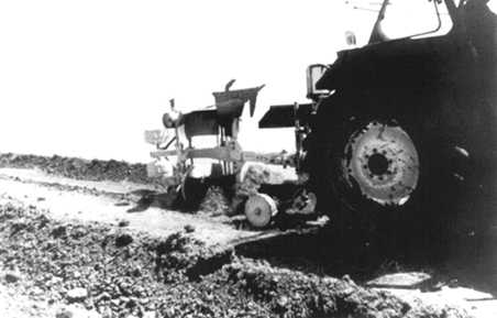