Water may be moved by the application of any one (or any combination) of six different mechanical principles, which are largely independent, i.e. by:
Families of pumps and lifting/propelling devices may be classified according to which of the above principles they depend on. Table 5 is an attempt to classify pumps under the categories given above. It will be seen that most categories sub-divide into the further classifications "reciprocating/cyclic" and "rotary". The first of these relates to devices that are cycled through a water-lifting operation (for example a bucket on a rope is lowered into the water, dipped to make it fill, lifted, emptied and then the cycle is repeated); in such cases the water output is usually intermittent, or at best pulsating rather than continuous. Rotary devices were generally developed to allow a greater throughput of water, and they also are easier to couple to engines or other types of mechanical drive. Therefore, by definition, a rotary pump will generally operate without any reversal or cessation of flow, although in some cases the output may appear in spurts or pulsations.
Before considering the differences between the diverse options available for lifting water, it is worth briefly noting the factors they all have in common. Virtually all water lifting devices can best be characterized for practical purposes by measuring their output at different heads and speeds. Normally the performance of a pump is presented on a graph of head versus flow (an H-Q graph, as in Fig. 16 ) and in most cases curves can be defined for the relationship between H and Q at different speeds of operation. Invariably there is a certain head, flow and speed of operation that represents the optimum efficiency of the device, i.e. where the output is maximized in relation to the power input. Some devices and pumps are more sensitive to variations in these factors than others; i.e. some only function well close to a certain design condition of speed, flow and head, while others can tolerate a wide range of operating conditions with little loss of efficiency. For example, the centrifugal pump characteristic given in Fig. 16 shows an optimum efficiency exceeding 80% is only possible for speeds of about 2000 rpm.
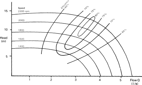
Fig. 16 Typical curves showing relationship between head, flow, speed and efficiency (example given for a centrifugal pump)
The rest of this Section describes in some detail each of the devices given in the Taxonomy of Pumps and Water Lifting Devices of Table 5.
These are all variations on the theme of the bucket, are hand-held and must be the earliest artificial methods for lifting and carrying water. The watering can is effectively a bucket with a built-in sprinkler and represents an efficient, but labour intensive method for irrigating very small land-holdings. Artisan-made watering cans are quite widely used in Thailand. Scoops, bailers (Fig. 17) and the swing-basket (Fig. 18) represent methods of speeding up the process of filling, lifting and emptying a bucket; the latter also uses two people rather than one and thereby increases the mass of water that can be scooped in each swing. These are more fully described in Section 4.2 in the context of using human muscle power, since they have evolved in such a way as to fit the human prime-mover but to be unsuitable for any kind of mechanization. They are rather inefficient as water is lifted over lm and allowed to fall back to 0.3-0.5m, which is the approximate operating head for devices of this kind.
Table 5 TAXONOMY OF PUMPS AND WATER LIFTS
|
Category and Name |
Construction |
Head |
Power |
Output |
Efficiency |
Cost |
Suction Lift? |
Status |
|
|
I DIRECT LIFT DEVICES |
|||||||||
|
Reciprocating .'cyclic |
|||||||||
|
Watering car. |
1 |
>3 |
* |
* |
* |
* |
x |
√ | |
|
Scoops and bailers |
1 |
>1 |
* |
** |
* |
* |
x |
√ |
|
|
Swing basket |
1 |
>1 |
* |
** |
* |
* |
x |
√ |
|
|
Pivoting gutters and "dhones" |
2 |
1-1.5 |
* |
** |
** |
** |
x |
√ | |
|
Counterpoise '.lit or "Shadoof" |
2 |
1-4 |
* |
** |
** |
** |
x |
√ |
|
|
Rope & bucket and windlass |
1 |
5-50 |
* |
* |
* |
* |
x |
√ | |
|
Self-emptying bucket or "mohte" |
2 |
3-8 |
** |
*** |
* |
** |
x |
√ |
|
|
Reciprocating bucket hoist |
3 |
100-500 |
**** |
**** |
*** |
**** |
x |
x |
|
|
Rotary/continuous |
|||||||||
|
Continuous bucket pump: |
2 |
5-50 |
* * |
** |
*** |
** |
x |
√ |
|
|
Persian when', or "tablia" |
2 |
3-10 |
** |
*** |
*** |
** |
x |
√ | |
|
Improved Persian wheel "zawaffa" |
2 |
3.15 |
*** |
**** |
**** |
*** |
x |
√ | |
|
Scoop wheels or "sakia" |
2 |
>2 |
** |
**** |
**** |
**** |
x |
√ | |
|
Waterwheels or "noria" |
2 |
>5 |
* |
** |
** |
** |
x |
√ |
|
|
II DISPLACEMENT PUMP |
|||||||||
|
Reciprocating/cyclic |
|||||||||
|
Piston/bucket pumps |
2& 3 |
2-200 |
*** |
*** |
***** |
**** |
√ |
√ |
|
|
Plunger pumps |
3 |
100-500 |
*** |
** |
**** |
***** |
√ |
? |
|
|
Diaphragm pumps |
3 |
5-10 |
** |
*** |
**** |
*** |
√ |
√ |
|
|
"Petropump" |
3 |
10-100 |
** |
** |
***** |
**** |
√ |
? |
|
|
Semi-rotary pumps |
3 |
5-10 |
* |
** |
** |
** |
√ |
x |
|
|
Gas or vapour displacement |
3 |
5-50 |
**** |
**** |
*** |
*** |
√ or x |
? |
|
|
Rotary/continuous |
|||||||||
|
Gear and lobe pumps |
3 |
10-20 |
* |
* |
** |
*** |
√ |
X |
|
|
Flexible vane pumps |
3 |
10-20 |
** |
*** |
*** |
**** |
√ |
X |
|
|
Progressive cavity (Mono) |
3 |
10-100 |
*** |
*** |
**** |
**** |
x |
? |
|
|
Archimedean screw |
3 |
>2m |
** |
**** |
*** |
*** |
x |
√ |
|
|
Open screw pumps |
3 |
>6m |
**** |
***** |
**** |
***** |
x |
√ | |
|
Coil and spiral pumps |
2 |
>6m |
** |
** |
*** |
*** |
x |
√ | |
|
Flash-wheels & treadmills |
2& 3 |
>2 m |
** |
**** |
** |
** |
x |
√ |
|
|
Water-ladders "Dragon spines" |
2 |
>2m |
** |
*** |
*** |
*** |
x |
√ | |
|
Chain (or rope) and washer |
2 & 3 |
3-20m |
*** |
*** |
**** |
**** |
x |
√ | |
|
Peristaltic pump |
3 |
>3m |
* |
* |
*** |
*** |
√ |
x |
|
|
Porous rope |
3 |
3-10m |
** |
** |
? |
? |
x |
? |
|
| III VELOCITY PUMPS | |||||||||
|
Reciprocating/cyclic |
|||||||||
|
|
Inertia and "joggle" pumps | 2& 3 |
2-4 |
* |
** |
**** |
** |
x |
√ |
|
|
Flap valve pump | 1 & 2 |
2-4 |
* |
* |
** |
* |
x |
√ |
|
|
Resonating joggle pump | 2 |
2-10 |
** |
**** |
**** |
*** |
x |
? |
|
|
Rebound inertia | 3 |
2-60 |
** |
* |
**** |
*** |
√ |
x |
|
Rotary/continuous |
|||||||||
|
Propeller (axial flow) pumps |
3 |
5-3 |
**** |
***** |
**** |
**** |
x |
√ |
|
|
Mixed flow pumps |
3 |
2-10 |
**** |
***** |
**** |
**** |
x |
√ |
|
|
Centrifugal (volute) pumps |
3 |
3-20+ |
***** |
***** |
**** |
*** |
√ |
√ |
|
|
Centrifugal (turbine) pumps |
3 |
3-20+ |
***** |
***** |
**** |
**** |
√ | √ | |
|
Centrifugal (regenerative) pump; |
3 |
10-30 |
*** |
*** |
*** |
**** | √ |
x |
|
|
Jet pumps (water, air or stream) |
3 |
2-20 |
*** |
** |
** |
*** |
x |
x |
|
|
IV BUOYANCY PUMPS |
|||||||||
| Air lift | 3 |
5-50 |
** |
*** |
** |
**** |
x |
x |
|
|
V IMPULSE PUMPS |
|||||||||
|
Hydraulic ram |
3 |
10-100 |
** |
** |
*** |
*** |
x |
√ |
|
|
VI GRAVITY DEVICES |
|||||||||
|
Syphons |
1, 2 & 3 |
1.(1-10) |
� |
***** |
� |
** |
� |
√ |
|
|
Qanats or foggara |
2 |
� |
� |
** |
***** |
� | � |
√ |
|
|
Construction: 1 Basic 2 Traditional 3 Industrial |
Very low |
*** |
Medium-high |
***** |
Yes √ |
Yes √ |
|
Low-medium |
*** |
High |
***** |
No x |
Possible ? |
|
|
Medium |
*** |
Unlikely x |
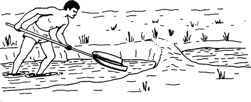
Fig. 17 The scoop used as a simple hand tool
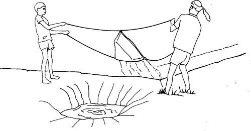
Fig. 18 The swingbasket in use (after T. Schioler [24])
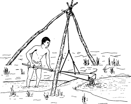
Fig. 19 Scoop with a rope support
The next: stage of technical advance is to support the mass of water being lifted by mounting the scoop or bucket on a suspended pivoted lever to produce a swinging scoop (Fig. 19) or a see-sawing gutter or "dhone" (Fig. 20) which also operate through low lifts (0.5-lir.) at relatively high speed. The water container can be balanced with a weight; Fig. 21 shows a counterpoise lift, alias water-crane or "shadoof".
If the terrain permits, such as on a sloping river bank, several "shadoofs" can be used to lift water in stages through a greater height than is possible with one.
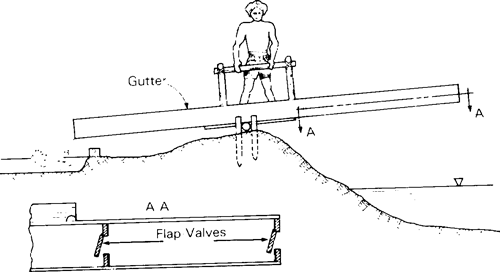
Fig. 20 Dhone as used in Bangladesh
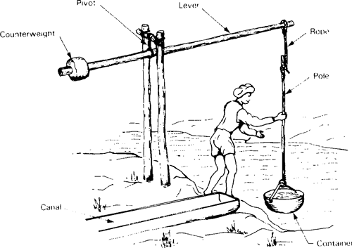
Fig. 21 Counterpoise lift
To increase the lift it becomes necessary to introduce a rope to pull the container of water from the source to a level where it can be tipped into the conveyance channel. There is therefore a family of devices for pulling up a container of water on a rope. The simplest form for this is a rope and bucket, which in an improved form has a simple windlass, i.e. a hand operated winch, to increase the leverage and hence the size of bucket that can be lifted.
The output of such systems is generally too snail for irrigation, (they tend to be used mainly for domestic or livestock water supply duties), but by powering the device with animals, usually oxen, sufficient water can be lifted to irrigate even through heads of 5-10m. This encouraged the evolution of the "self-emptying bucket", known in India as a "mohte", (Figs. 22 and 92). These commonly have a bucket made of leather or rubber, with a hole in its bottom which is held closed by a flap which is pulled tight by a second rope harnessed to the animals. The number in use today is still in the order of a million or more, so this device remains of considerable importance in some regions. Mohtes are discussed in more detail under Section 4.3 dealing with animal power as a prime mover.
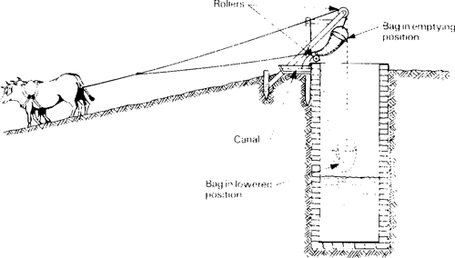
Fig. 22 Self-emptying mohte with inclined tow path
It generally improves both efficiency and hence productivity if the water lifting element can move on a steady circular path rather than being cycled or reciprocated. The reason for this is that the energy input to any water lifting device is usually continuous, so that if the output is intermittent, unless energy can be stored during the parts of the cycle when no water is lifted, it is lost. Therefore reciprocating/cyclic devices tend to be less efficient than rotary devices; this is not a firm rule however, as some reciprocating devices include means to store energy through the non-productive part of the cycle while some rotary devices are less efficient for other reasons.
An. obvious improvement to the simple rope and bucket is to fit numerous small buckets around the periphery of an endless belt to form a continuous bucket elevator. The original version of this, which is ancient in origin but still widely used, was known as a "Persian wheel" (Figs. 23, 94 and 95); the earliest forms consisted of earthenware pots roped in a chain which is hung over a drive wheel. The water powered "noria" (Figs. 24, 151 and 152), a water wheel with pots, buckets or hollow bamboo containers set around its rim, is similar in principle except the containers are physically attached to the drive wheel circumference rather than to an endless belt suspended from it.
The flow with any of these devices is a function of the volume of each bucket and the speed at which the buckets pass across the top of the wheel and tip their contents into a trough set inside the wheel to catch the output from the buckets. Therefore, for a given power source and speed of operation roughly the same number of containers are needed regardless of head. In other words, a higher head Persian wheel requires the buckets to be proportionately more spaced out; double the head and you more or less need to double the spacing.
The Persian wheel has been, and still is, widely used particularly in the north of the Indian sub-continent and is discussed in more detail under Section 4.3 on Animal Power, while the noria was widely used in China, S.E. Asia and to some extent in the Middle East and being normally water powered is discussed in more detail in Section 4.9. Both devices are tending to be replaced by more modern mechanical water lifting techniques as they are old-fashioned and low in output. It should be noted that the term "Persian wheel" is sometimes used to describe other types of animal powered rotary pumps.
Although Persian wheels and norias are mechanically quite efficient, the main source of loss from these types of device is that some water is spilled from the buckets and also there is a certain amount of friction drag caused when the buckets scoop up water, which again reduces efficiency. Also, the Persian wheel is obliged to lift the water at least 1 m (or more) higher than necessary before discharging it into a trough, which can significantly increase the pumping head, particularly in the case of low lifts. The traditional wooden Persian wheels also inevitably need to be quite large in diameter to accommodate a large enough collection trough to catch most of the water spilling from the pots; this in turn requires a large well diameter which increases the cost.
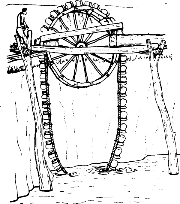
Fig. 23 Persian wheel

Fig. 24 Noria
Some performance figures for animal powered Persian wheels are given in Molenaar; [1 ].
|
Height lifted |
Discharge |
|
9m |
8-10m3/h |
|
6m |
10-12m3/h |
|
3m |
15-17m3/h |
|
1.5m |
20-22m3/h |
Depending on the assumption used for the power of the animals in the above examples, the implication is that the efficiency is in the order of 50% at medium lifts such as 6m and perhaps marginally better at higher lifts but worse at lower lifts.
The water-powered noria uses the same principle as the Persian wheel and therefore also needs to be of larger diameter than the pumping head, which either limits it to very low lift pumping or requires very large, cumbersome and expensive construction. Small, low-lift norias, used in Thailand and China, are very inexpensive while much larger norias are used in Vietnam and Syria. Some of the largest in Syria exceed 10m in diameter, but in relation to their size they tend to be unproductive compared with more modern pumping systems. A fuller description of Vietnamese and other norias is given in Section 4.9
Traditional wooden Persian wheels were fitted with earthenware water containers, but a variety of all-metal improved Persian wheels have been built, some as commercial products, in China, India, Pakistan and Egypt. Metal Persian wheels can be made smaller in diameter, which reduces the extra height the water needs to be lifted before it is tipped out of the containers, and also reduces the well diameter that is necessary.
A modified version of the Persian wheel used in Syria and also in Egypt (where it is called the zawaffa or jhallar) includes internal buckets within the drive wheel which catch the water and direct it through holes in the side plate near the hub into a collection trough; Fig. 25. This reduces both splashing and spillage losses and the extra height above the collection channel at which the water is tipped. Roberts & Singh [13] gave figures for a modernised metal Persian wheel, of 153m3/h lifted through 0.75m. This implies that efficiencies as high as 75% are possible with modernised devices, which are rather good.
The scoop-wheel (sakia in Egypt where it originated) has some factors in common with the noria. Although widely used in Egypt it has failed to become popular anywhere else. It is however an efficient and effective device; Fig. 26.
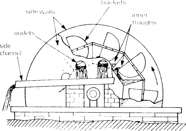
Fig. 25 Zawaffa type Persian wheel
(side wall shown partially removed)
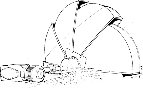
Fig. 26 Sakia or Tympanum (electrically powered in this case)
It consists of a large hollow wheel with scoops around its periphery, which discharges water at or near its hub rather than from its top. The diameters for sakias range from about 2-5m; since water discharges at their hub level, the rule of thumb used in Egypt is that a sakia will lift water through a head of half its diameter less 0.7 m, to allow for the depth of submergence of the rim in order to scoop up water effectively. Therefore sakias of diameters from 2-5m will lift water from 0.3-1.8m respectively.
Sakias are now normally made from galvanized sheet steel. Second-hand vehicle roller bearings are commonly used to support the substantial weight of a sakia and its water contents. Most sakias are animal powered, but they are increasingly being driven by either mains electric motors or small engines, via suitable reduction gearing. The normal operating speed is 2-4 rpm for animal-driven sakias, and 8-15 rpm for motorised or engine-powered units.
Various different spiral shapes have evolved for the internal baffle plates in the sakia, and the Hydraulic Research and Experimental Station (HRES) in Egypt tested various models to try to determine the optimum design. The best shaped designs, such as in Fig. 27, were measured as being as much as 50% better than the worst. Since some 300 000 sakias are in use in the Nile valley and Delta, optimization of the design could yield substantial aggregated benefits. An important feature of the the three most successful sakia variants tested is that the outer compartments divided by the internal baffle plates discharge first into individual collection chambers which in turn discharge through holes surrounding the hub instead of having a common discharge orifice as on the more traditional designs. This prevents water running back into the compartment adjacent to it.
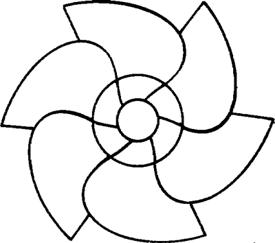
Fig. 27 The Fathi is the optimum design of Sakia
The types of sakia with separate discharge points for each compartment are distinguished by the generic name "tablia". A further advantage of the tablia type of device is that the water discharges a few centimeters above the centre shaft and therefore increases the useful head in relation to the diameter; especially with smaller machines. Typically a 3m tablia will lift water 1.5m compared with 0.90m for a centre-discharge sakia.
Another important conclusion from the tests by HRES was that for wheels operated in the 2-15rpm range, 6-8 compartments provide the optimum discharge. According to Molenaar [1], the following performance might be expected from traditional sakia designs:
|
diameter of |
head |
output |
| 5m |
1.8m |
36m3/h |
| 4m |
1.3m |
51m3/h |
| 3m |
0.9m |
75m3/h |
| 2m |
0.3m |
114m3/h |
Comparison of the above outputs with those from a traditional persian wheel indicate that the sakia is somewhat more efficient, although of course it cannot lift water as high as is possible with a persian wheel.