9. SOIL PERMEABILITY
9.0 Why is it important to determine soil permeability?
|
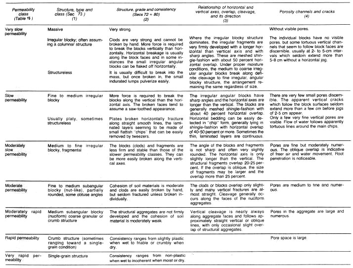
Soil permeability is the property of the soil to transmit water and air and is one of the most important qualities to consider for fish culture. |
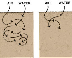 |
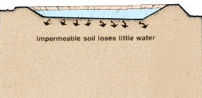
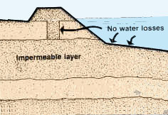
| A pond built in impermeable soil will lose little water through seepage. |
|
 |
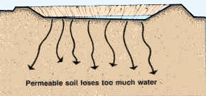
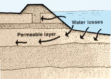
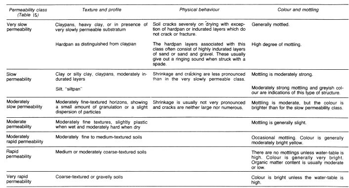
| The more permeable the soil, the greater the seepage. Some soil is so permeable and seepage so great that it is not possible to build a pond without special construction techniques. You will learn about these techniques in a later volume in this series. |
 |
The dikes of the pond should be built with soil which will ensure a good water retention. Again, soil quality will have to be checked with this in mind.
 |
 |
9.1 Which factors affect soil permeability?
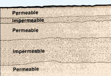
Many factors affect soil permeability. Sometimes they are extremely localized, such as cracks and holes, and it is difficult to calculate representative values of permeability from actual measurements. A good study of soil profiles provides an essential check on such measurements. Observations on soil texture, structure, consistency, colour/mottling, layering, visible pores and depth to impermeable layers such as bedrock and claypan* form the basis for deciding if permeability measurements are likely to be representative.
Note: you have already learned that soil is made up of a number of horizons, each of them usually having different physical and chemical properties. To determine the permeability of soil as a whole, each horizon should be studied separately.
9.2 Soil permeability relates to soil texture and structure
The size of the soil pores is of great importance with regard to the rate of infiltration (movement of water into the soil) and to the rate of percolation (movement of water through the soil). Pore size and the number of pores closely relate to soil texture and structure, and also influence soil permeability.
Permeability variation according to soil texture
Usually, the finer the soil texture, the slower the permeability, as shown below:
|
|
Example
Average permeability for different soil textures in cm/hour
|
Permeability variation according to soil structure
Structure may greatly modify the permeability rates shown above, as follows:
1 This may vary according to the degree to which the structure is developed. It is common practice to alter the soil structure to reduce permeability, for example, in irrigated agriculture through the puddling of rice fields and in civil engineering through the mechanical compaction* of earthen dams. Similar practices may be applied to fish-ponds to reduce water seepage. |
|||||||||||||
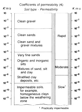
For agriculture and conservation uses, soil permeability classes are based on permeability rates, and for civil engineering, soil permeability classes are based on the coefficient of permeability (see Tables 15 and 16).
For fish culture, two methods are generally used to determine soil permeability. They are:
- The coefficient of permeability;
- The seepage rate.
For the siting of ponds and the construction of dikes, the coefficient of permeability is generally used to qualify the suitability of a particular soil horizon:
- Dikes without any impermeable clay core may be built from soils having
a coefficient of permeability less than
K = 1 x 10⁻⁴ m/s; - Pond bottoms may be built into soils having a coefficient of permeability less than K = 5 x 10⁻⁶ m/s.
For pond management, the seepage rate is generally used:
- In commercial pond culture, an average seepage rate of 1 to 2 cm/d is considered acceptable, but corrective measures should be taken to reduce soil permeability when higher values exist, particularly when they reach 10 cm/d or more.
9.4 Measurement of soil permeability in the laboratory
When you take an undisturbed sample to a testing laboratory, to measure permeability, a column of soil is placed under specific conditions such as water saturation and constant head of water. The result will be given to you either as a permeability rate (see Table 15), or as a coefficient of permeability (see Table 16).
9.5 Measurement of soil permeability in the field
To measure soil permeability in the field, you can use one of the following tests:
- The visual evaluation of the permeability rate of soil horizons;
- A simple field test for estimating soil permeability;
- A more precise field test measuring permeability rates.
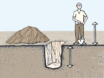
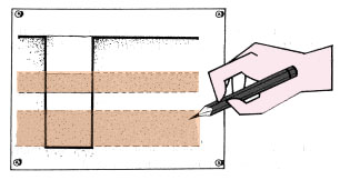
The visual evaluation of the permeability rate of soil horizons
The permeability of individual soil horizons may be evaluated by the visual study of particular soil characteristics which have been shown by soil scientists to be closely related to permeability classes. The most significant factor in evaluating permeability is structure: its type, grade, and aggregation characteristics, such as the relationship between the length of horizontal and vertical axes of the aggregates and the direction and amount of overlap.
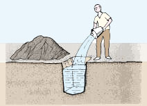
Although neither soil texture nor colour mottling alone are reliable clues, these soil properties may help to estimate permeability when considered together with the structural characteristics. To evaluate visually the permeability of soil horizons:
- Examine a fresh soil profile in an open pit;
- Determine the soil horizons present;
- Using Table 17A, evaluate the permeability class to which each horizon belongs, carefully studying the structural characteristics of the soil;
- Confirm your results through the other soil properties shown in Table 17B;
- Ranges of permeability rates may then be found in Table 15.
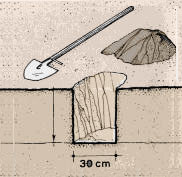
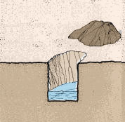
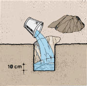
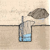
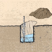
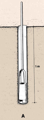
A simple field test for estimating soil permeability
 |
 |
|
|
 |
 |
 |
|
|
 |
|
|
A more precise field test for measuring permeability rates
Note: you could also use the visual method (see Tables 17A and 17B) to estimate permeability. |
|
|
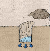
Note: water seeps into the soil both horizontally and vertically, but you need only be concerned with the vertical water seepage because this is mainly what happens in ponds. |
 |
 |
 |
|
|
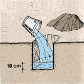 |
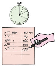
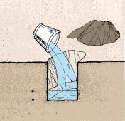
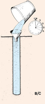
- At first, the water will seep down rather quickly, and you will have
to refill as it disappears. When the pores of the soil are full of water,
seepage will slow down. You are then ready to measure the permeability
of the soil horizon at the bottom of the hole;
 |
 |
|
 |
 |
|
|
 |
|
 |
|
If the permeability rate is faster than 5 mm/h, this may be owing to a strongly developed structure in the soil. In such cases, you try to reduce the permeability rate by destroying the structure, as follows:
 |
 |
|
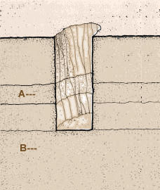 |
Note: when building your pond, you do not necessarily need to remove a shallow permeable layer if there is a deeper layer of soil which is not permeable and will serve to hold the water. You must, however, build the pond dikes down to the deeper non-permeable layer to form an enclosed basin and to avoid horizontal water seepage (see Section 9.0).
9.6 Determining coefficients of permeability
To obtain a more accurate measurement of soil permeability, you can perform the following test in the field which will give you a value for the coefficient of permeability:
 |
 |
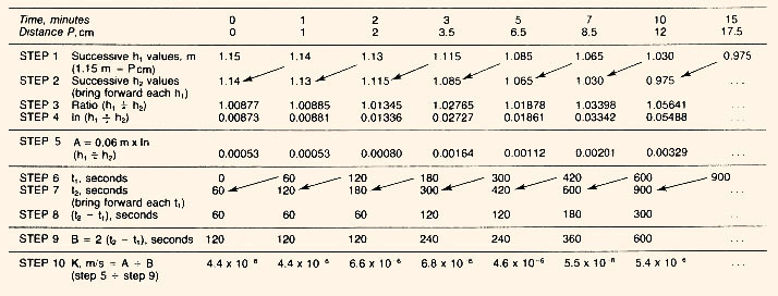
Example
Rate becomes constant 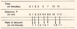 |
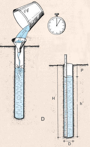 |
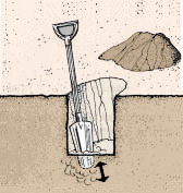
- Measure exactly the total depth of the hole (H) and its diameter (D). Express all measurements in metres (m): for example
H = 1.15 m and D = 12 cm or 0.12 m
- For each of the above two consecutive measurements of time/distance, calculate the coefficient of permeability K using the following formula:
K= (D÷2) x In (h1÷ h2) / 2 (t2- t1)
where (D ÷ 2) is the radius of the hole or half its
diameter in metres; In refers to the Napierian or natural
logarithm;
h1 and h2 are the two consecutive depths
of water in metres, h1 at the start and h2 at the
end of the time interval;
(t2 - t1 ) expresses the time interval between two
consecutive measurements, in seconds;
Note: the h-values may be readily calculated as the differences between the total depth of the hole H and the successive P values. Be careful to express all the measurements in metres and seconds so as to obtain K in m/s.
- Now compare your K values (in m/s) with those in Table 16.
Example
If (D ÷ 2) = 0.12 m ÷ 2 = 0.06 m and H = 1.15 m, calculations of the various K values are made progressively according to the formula (see Table 18).
Note: for obtaining the natural logarithm of (h1 ÷ h2), you will have to use either a logarithmic table or a pocket calculator.
Remember that 10 - 6 = 0.000001 and 6.8 x 10-6 = 0.0000068, the negative exponent of 10 reflecting the decimal place to be given to the multiplicant.
If you wish to compare a K value (m/s) with permeability rates (cm/day), multiply K by 8 640 000 or 864 x 104 such as for example:
K = 1 x 10⁻⁵ m/s = 86.4 cm/day