1. In addition to the pond soil itself, you might use a range of different materials for the fish farm, for example for foundations, water supply and water control devices. The choice ranges from locally available materials such as bamboo and wood to bricks, cement blocks, concrete and plastics (for pipes), for which you may have to go to specialized dealers.
|
|
|
2. The choice of construction materials essentially depends on their suitability, their local availability and the amount of money you are prepared to invest.
3. If you are a beginner fish farmer and your farm is very small, it is best to use simple structures and not to spend too much on materials. As you gain experience and wish to expand, your investments may increase, and more permanent, better structures may be built.
4. It you plan to build a large fish farm, you should select the most suitable permanent structures from the start.
 |
 |
|
 |
 |
5. The materials generally have to be transported to the construction site. To plan this properly and help estimate the cost of transport and handling, use Table 5, which gives the weight per unit volume (kg/m3) of common basic materials.
|
TABLE 5
|
Reinforcement steel bars
|
|||||||||||||||||||||
| Note: for granular materials, these figures are bulk densities, i.e. including the pore space between the particles. The actual density is higher | ||||||||||||||||||||||
3. When harvesting fresh bamboo, avoid letting them dry for too long; they shrink as they dry, and small cracks develop, which can weaken the bamboo for later use as a water pipe.
4. To produce good quality bamboo pipes:
(a) Cut mature bamboo and carry
them out of the forest.
(b) If necessary store bamboo in
the shade, covering them with branches or large leaves.
(c) Partially break or drill the
partition walls inside the culms (see paragraphs 6 and 7).
(d) As soon as possible, immerse
the freshly cut bamboo into water (in a reservoir, river or pond).
(e) To desap them, leave them in
the water for six to eight weeks to extract the chemical substances present in the bamboo
culm wall and to improve the durability of the pipes.
(f) After desapping, remove all
remaining parts of the partition walls in the bamboo pipe.
(g) The bamboo pipe is ready for
use.
Note: if you harvest bamboo during the dry season or at the beginning of the rainy season, desapping will be easier, and the quality of the pipes will be better.
 |
 |
 |
 |
 |
5. There are two simple ways of removing the partition walls of bamboo: drilling them or cutting them out. If the walls are tough, they might be too hard to drill.
6. Drill the partition walls manually with a circular bit, which you can easily make yourself.
|
(a)Bell out one end of a short length of steel pipe to increase the diameter. |
(b)Sharpen the edge with a file. |
|
|
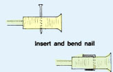
(c)Push a length of bamboo of sufficiently small diameter into the pipe to act as a handle. |
(d) Secure this bamboo to the pipe by drilling a small hole through the assembly and inserting a nail in the hole. |
|
|
(e) Bend the nail to fix it into place, making sure it does not stick out too far and cause the drill to jam. |
(f) For each bamboo, first use the smallest diameter bit and bore a hole through each partition wall. |
|
|
(g) Later, for example after desapping the pipes, progressively enlarge these holes with larger diameter bits.
|
Note: you may need several bits for various sizes of bamboo. To drill through or break partition walls, you may need the help of other people.
|
7. To cut out the partition walls, proceed as follows.
|
(a) Fix the bamboo culm on the ground, for example between strong stakes, to keep it from rotating . |
(b) Using a saw, cut a thin slit on each side of the first node where the partition wall is known to be. |
|
|
(c) Using a sharp wood chisel, cut out a small square piece from the top part of the bamboo culm. Cut it as cleanly as possible.
|
(d) Keep all the squares that you cut out. You will need them later. |
|
|
(e) Through the hole, cut out the partition wall with the wood chisel.
|
(f) Proceed as above for each partition wall, making sure that the square hole is always cut along the same line on top of the bamboo. |
| (g) When you have removed the last partition
wall, place the bamboo vertically and take out all the loose pieces from
inside the bamboo.
|
(h) Put the little square pieces you have kept aside back into the holes and secure them with a piece of string or wire.
|
|
| (i) Cut one end of the bamboo obliquely. The water pipe is now ready |
 |
Using bamboo as a construction material |
||
| 8. Bamboo used for construction is cut, immersed and stored
in the same way as the bamboo for pipes, although cutting internal walls
is not so important. However, if you are using the bamboo for piling (driving
them into the ground), removing the walls helps anchor the bamboo. 9. Wherever possible use lashings or ties to connect the pieces, as nails and screws will cause splitting and will weaken the structure. |
 |
|
|
|
|
|
|
A Floor framing B Saddle joint C Inset block support D Branch node support |
10. The characteristics of wood, in particular density*, hardness and natural durability, vary greatly. It is best to select the wood variety according to its use (see Table 6):
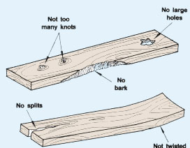
11. Wood used as a permanent construction material should be free from bark wood and should not have any large holes or too many knots. It should be well dried and should not be twisted or split. It should be stored flat in a dry place with good air circulation.
 |
 |
|
 |
12. For temporary use, e.g. to make casting forms for concrete (see Section 3.4), use light, cheap wood. If you are re-using it, make sure that the surfaces facing the concrete are even and are free from nails or splinters. To build water control structures, use heavier, preferably very durable wood, such as iroko or makore.
13. To increase durability, especially of wood in permanent contact with the soil, you can treat its surface.
|
(a) Burn the surface of the wood (e.g. the bottom part of poles).
|
(b) Use tar (e.g. on the bottom part of poles or the outside of a structure near soil). If you can, it is better to apply hot tar.
|
|
|
(c) Use waste motor oil diluted with a solvent such as paraffin which, when applied, will penetrate the wood and will help to force moisture out.
|
(d) Use special wood preservatives. These are more expensive and are usually copper, lead, zinc, or tin compounds in a solvent. As these are poisonous materials they should be handled very carefully.
|
Note: for the best results with tar, oil or other preservatives, apply the preservative generously and allow plenty of time to let it get into the wood. Put on several coats of preservative or dip the wood into a can or trough of preservative for at least 30 minutes. Make sure the end grain of the wood is properly treated, as this is where decay often starts.
 |
 |
1. There are many different kinds of bricks.Lightweight hollow bricks are usually not strong enough for fish farm use. Solid burnt clay bricks are commonly used for fish farms. They are made of clay, air dried and fired in a special kiln. Their quality greatly depends on this firing. You should reject bricks which are too uneven, cracked, and either burnt too much or not enough.
2. In places where they are available, industrially made bricks, either solid or with a slight hollow on each side, or with two or three small "finger holes", are also suitable. "Engineering bricks", usually a yellow/ black colour, are also useful for foundations and heavily loaded areas, as they are much stronger and resist penetration by water.
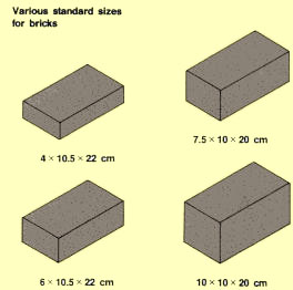
3. Bricks are generally available in standard sizes, which vary from country to country. The following are examples of various standard sizes 4 x 10.5 x 22 cm, 6 x 10.5 x 22 cm, 7.5 x 10 x 20 cm and 10 x 10 x 20 cm.
4. Bricks are used together with cement mortar (see Section 3.3). They should be stored and handled carefully to avoid excessive breakage. They should be well soaked in water for at least 30 minutes before use.
 |
 |
5. Cement or concrete blocks are made of a mix which is cast and pressed into a special form. Concrete blocks can be made on site if needed, but care should be taken to make sure they are properly cast (see Section 3.4, paragraph 57). Blocks should be at least 28 days old before they are used for construction.
6. Both hollow and solid cement blocks are produced. They are available in several standard sizes, usually with a length of from 40 to 50 cm, a height of 20 cm and a thickness of from 5 to 20 cm. The following are examples of various standard sizes: 5 x 20 x 40 cm,10 x 20 x 40 cm and 20 x 20 x 40 cm. Blocks are sometimes available in different weights: generally the heavier the block, the stronger. Blocks are used together with cement mortar (see Section 3.3). They should be properly stored and handled. They should be well wetted with water before use.
7. Standard clay bricks and cement blocks have a low resistance to humidity. They should, therefore, preferably not be used for foundations or underground constructions. In the presence of water, they should be well protected by impervious surfacing made of rich mortar (see Section 3.3).
|
Kinds of blocks
 |
8. Stones are used in some areas for construction, usually for walls and for lining water canals, dikes and spillways. Their characteristics depend on the type of rock they come from:
9. Stones are used either "dry", without any mortar or jointing material, by carefully selecting and fitting them together or, more commonly "wet", by setting them in mortar.
10. For walls, unless you have cut stones, it is usually important to have a range of sizes, using smaller stones to fill in the gaps and secure the larger stones in place.
11. You will also need larger stones at the corners, at intervals along the wall and across the width of the wall, to give the wall strength and stability.
12. Usually, stones with irregular, rough edges make stronger walls. For lining canals, small, smooth, rounded stones are best as they let water flow past more easily.
 |
 |
3.3 Cement mortars |
||
|
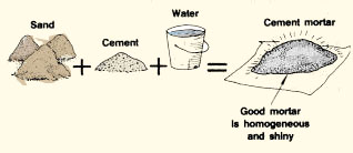
1. A cement mortar is a well-proportioned mixture of sand, cement and water. It is mainly used for joining together and surfacing materials such as stones, bricks and cement blocks. A good mortar is homogeneous, soft and shiny. It has a smooth appearance and a plastic consistency. 2. To prepare a good mortar, it is very important to use the proper ingredients and to mix them thoroughly in the right proportions. |
Mixing cement mortar
 |
|
Selecting the sand |
||
|
3. It is best to use a clean, well-graded mixture of coarse to fine sand, with particle sizes varying from 0.2 to 5 mm. If possible, you should avoid using sea beach sand or sand deposits contaminated with salts. If you have to use these materials, you should wash the sand well. 4. Natural sand deposits can sometimes be found not too far from the construction site, for example in stream beds, dried-up lake or stream areas or quarries, but well-graded sands seldom occur naturally. In many cases, you will have to sift the sand through a 0.2 mm mesh screen to eliminate the finest particles. If there are particles larger than 5 mm, you should also eliminate them, using a 5-mm mesh screen. Checking the cleanliness of the sand5. The sand should be free from silt, clay and organic materials. |
 |
|
6. A simple test to check the cleanliness of the sand is as follows:
(a) Obtain a clear, wide-mouthed glass jar.
(b) Fill the bottom of the jar with sand 5 cm deep.
(c) Add clean water until the jar is three-quarters full.
(d) Add, if available, two teaspoons of common table salt per litre of water.
(e) Close the jar and shake it vigorously for one minute.
(f) Let it stand for three hours.
(g) Check the sand surface. If there is silt present, it will form a layer on
top of the sand.
(h) If there are more than 3 mm of silt, the sand must be washed.
 |
 |
 |
 |
7. Another simple test to check the cleanliness of sand is as follows:
|
(a) Take a handful of sand and squeeze it. |
(b) Throw it away. |
|
|
(c) It your hand is clean and free of sticky dust, the sand is clean. |
(d) If your hand is dirty and sticky, the sand is dirty. |
8. If there is too much silt, you will have to wash the sand before using it. Repeat the following procedure until all your sand is clean.
|
(a) Put sand in a large, clean container such as a 200-litre metal drum. |
(b) Cover the sand with clean, fresh water. |
|
|
(c) Stir vigorously. |
(e) Pour off the dirty water. |
(g) Store the clean sand, so as to keep it from being recontaminated.
9. You can store clean sand on the construction site, for example on a timber floor with low side walls as shown below.
|
A plank floor with low walls makes a good storage
for clean sand  |
 |
|
 |
10. You should use ordinary Portland cement (OPC), which is the standard, most widely available type of cement. It has the characteristics of setting and hardening in the presence of water while producing heat and shrinking in volume.
11. Remember that a mortar too rich in cement will crack while hardening.
Note: Portland cement strongly deteriorates in the presence of waters rich in calcium sulphate (more than 0.5 g/l) or sodium chloride (more than 4 g/l). In such cases, for example in acid sulphate soils or near brackish waters, a sulphate-resistant cement should preferably be used for constructions (see Section 1.8, Soil 6). This particular type of cement should never be mixed with Portland cement. If it is not available, use a slightly richer mix of OPC (see paragraph 19), taking particular care in mixing, using and setting and making sure the cement has cured well before letting it come into contact with the soil or water.
12. Portland cement is usually classified according to its potential resistance to compression, which is usually either about 250 kg /cm2 or about 325 kg /cm2. For fish farm constructions you mostly use the "250" grade.
13. Portland cement is sold in thick paper sacks. The weight and volume of the sacks vary according to the country:
14. Check which system is used in your country to avoid errors when preparing cement mixes.
15. To guarantee the top quality of your cement, you should take the following precautions.
(a) Check the freshness of the cement before buying.
It should be free from any lumps which cannot be pulverized between thumb and
forefinger.
(b) Bring on site only the number of sacks needed for a short
period.
(c) Protect your cement from humidity. Store it off the ground
(a simple wooden platform is suitable) in a dry, well-sheltered place.
(d) Use the cement while it is as fresh as possible, and rotate
your stocks properly.
(e) Never use hardened cement, but throw it away.
16. The water should be clean and neutral or slightly alkaline (pH 7 to 8.5). It should be free from organic matter, oil, alkali or acid. Avoid using saltwater or a water too rich in sulphates (more than 250 ppm).
17. If you have to use brackish water or dirty water, add a tablespoon of soap powder for every sack of cement used. Dissolve the soap into a small amount of water and add it to the mix.
18. There are three basic types of mortar which you can prepare yourself, as shown in Table 7, according to their use. Remember that the richer a mortar is in cement, the more it will shrink, and the more it will be inclined to crack.
|
TABLE 7
* Quantity of the material to prepare 1 m3
of mortar with the addition of about 200 l of water |
||||||||||||||||||||||
19. In acid sulphate soils, the Portland cement proportion is normally increased by 10 to 20 percent.
20. If you need only small quantities of mortar, you can mix cement and sand by volume, in the following proportions:
21.You will need about 200 l of water per m3 of mix (about one part water for five parts mix).
22. To produce a good mortar, it is essential that you measure accurately the amounts of cement and sand to be mixed, according to the proportions required.
23. If you know the weight of one sack of cement, it is easy to calculate how many sacks you will need to use (seeTable 7).
24. If you plan to use the above proportions by volume, it is best to use a container of known volume, such as a 10-litre bucket or a 50-litre wheelbarrow. For larger quantities, you can easily build yourself a 100-litre bottomles wooden box with handles as shown.
25. A shovel may also be used for sand and cement, but you should take care to load the same amount each time. Even then this method is not very accurate.
|
Convenient containers for measuring sand and cement
 |
 |
|
 |
 |
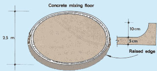
26. To prepare a good mortar, carefully proceed as follows:
| (a) Prepare a clean mixing area, for example
a metal sheet or a watertight wooden platform. As a rough guide, a 1-m2
area is enough for 50 kg of mix.
|
(b) Measure the quantity of sand required. If it is very dry, wet it a little before measuring. |
|
| (c) Spread the sand over the mixing area.
|
(d) Measure the quantity of cement required. |
| (e) Spread the cement on top of the sand.
|
(f) Mix the sand and cement together thoroughly, until the mix has a homogeneous colour. Be sure to mix in the bottom and side materials. |
|
|
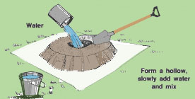
(g) Form a hollow in the middle, slowly add a little water in the hollow and moisten part of the mix. Work the water in by carefully moving the dry mix in toward the hollow. Be careful not to let water run away.
|
|
|
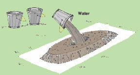
| (h) Repeat adding water little by little until the whole mix is moistened. Continue mixing thoroughly, adding just enough water to obtain a plastic consistency. The mortar should have a firm, smooth appearance. You should be able to make a clean slice into it with a trowel or shovel. It should sit on a trowel cleanly and firmly without loss of water and should spread smoothly. |
|
|
| 27. Remember: do not add too much water. |
28. The mortar should be used immediately after its preparation. A mortar should never be used after it has started to set, which you can tell is happening if the mix starts to become stiff and breaks up when spread. Avoid using mortar which has dropped from the working area.
29. The surfaces to come in contact with the mortar should be clean and rough. It is essential to wet them well before applying the mortar, for example by soaking bricks in water for 30 minutes and wetting cement blocks, so that they do not absorb the water from the mortar and reduce its strength. If you are working in dry conditions, be careful to keep the bricks or blocks wet.
 |
 |
30. Protect mortar from the sun's heat and from drying wind until it hardens to the point where its surface cannot be scratched with a fingernail. At this stage, setting is complete enough for normal requirements. In hot, dry conditions, you can protect the setting mortar by covering the areas concerned with wet sacking, or alternatively, by using a fine spray of water. However, be careful not to wash out the mortar.
 |
 |
|
 |
|
1. A cement concrete is a well-proportioned mixture of aggregates, cement and water. The aggregates* should be well graded so that when mixed they fit together with minimum pore space between them. These small remaining pores are filled up by the cement, which will then strongly bind the aggregates after its reaction with water. 2. The most important factors in making strong concrete are therefore:
3. There are two to three different grades of aggregates*, depending on the type of concrete required:
|
Enlarged detail of cement concrete
 |
|
|
Different grades of aggregates
 |
 |
4. Good natural sources of aggregate materials, sand and gravel for construction purposes (Table 8) are relatively infrequent. Well-graded soils that have the right range of particle sizes are particularly hard to find. If the soils contain some silt, they are only moderately suitable.
5. Soils where silt and clay predominate are poor natural sources of aggregates. Unsuitable soils are all those belonging to the other Unified Soil Classification (USC) groups (see Section 11.1, Soil, 6).
|
TABLE 8
|
6. Good concrete is a homogeneous mix without excess water. It is smooth and plastic. It is neither too wet and runny, nor too dry and crumbling.
7. To prepare good concrete, you should use the proper ingredients and mix them thoroughly in the right proportions. You have already learned which kinds of sand, cement and water to use (see Section 3.3). In the following sections, you will now learn about coarse aggregates and concreting.
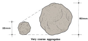
8. Your concrete is only as strong as the strength of its coarse aggregates. Therefore you should look for hard, dense and durable gravel and stones. These aggregates should never be lateritic (see Section 1.8, Soil,6).
9. If you have doubts about the strength of the coarse materials to be used, you can use the following test.
|
(a) Break some stones with a hammer.
|
(b) Break similar sizes of concrete pieces, and compare how difficult these are to break. |
(c) The stones are hard enough if they are more difficult to break than the concrete.
10. These coarse aggregates should preferably be neither flat in shape nor have sharp edges. The best materials have round or cubical shapes such as gravel from a stream bed or beach.
 |
 |
11. The aggregates should be clean and free from dirt and organic material. As with sand, you should wash them if necessary (see Section 3.3, paragraph 8).
|
Wash aggregates if necessary
 |
 |
12. Gravel and broken stones usually range in size from 0.5 to 6 cm across. For particular construction works, such as relatively thin concrete walls and slabs, you will have to use smaller broken stones.
Note: the sizes of the largest aggregate particles should never exceed one-quarter of the concrete thickness.
|
Aggregates should never exceed 1/4 of the concrete
thickness
 |
13. For heavier concrete work, particularly base slabs and heavy foundations, large boulders and rocks may be thrown in, provided the concrete can be packed around and over them.
14. In areas where rock aggregate is unavailable, broken brick is frequently used. It does not make strong concrete but can be acceptable for simple foundations and lightly loaded walls. Care should be taken in preparing, placing and curing the concrete to make it as strong as possible.
|
Large rocks may be used for base slabs if they
do not exceed 1/4 of the slab thickness  |
You can use broken bricks for simple foundations
 |
15. For general-purpose concrete work, there are three basic ways to determine the correct proportions of aggregates and cement:
16. For small concreting jobs and for repairs, use one of the first two methods. For larger concreting jobs, it is safest to use the third method.
17. The simple rules of thumb are given as guidelines for the preparation of four basic types of concrete, from a lean to a very rich mix.
18.Table 9 provides guidelines based on the weight of the cement for concretes containing from 150 to 400 kg cement per m3 . The quantity of water to be used depends greatly on the moisture content of the sand and gravel and must be judged when mixing the concrete.
|
TABLE
9
* "C"
refers to approximate concrete strength in newtons/mm2 |
19.Table 10 provides guidelines for similar types of concrete based on ratios by volume. The water quantity to be used is about 0.75 l per litre of cement. This should be checked while mixing.
|
TABLE 10
| |||||||||||||||||||||||||||||||||||||||||||||
Note: these figures (e.g. 1:2:4) are commonly used to describe concrete mixes; the weight mixes in Table 9, however, give more accurate specifications
20. The free-pore volume method is based on the fact that the cement should fill the pore spaces left free in the aggregates.
21. The volume of these free-pore spaces and the amount of cement paste required can be determined as follows.
|
(a) Take a sample of the ungraded aggregates you will be using to prepare your concrete.
|
(b) Sift this sample through a 5-mm screen to divide it into coarse aggregates (larger than 5-mm diameter) and fine aggregates (smaller than 5-mm diameter).
|
|
|
(c) Fill a small container of volume V1, such as a 15-litre bucket, with dry, coarse aggregates.
|
(d) Add water to the container and measure the water volume V2 required to fill it, in litres. (e) This volume equals the volume of fine aggregates and cement needed to fill the free-pore space of the coarse aggregates. |
|
|
(f) Measure a volume V2 of fine aggregates equal to the water volume determined in the previous step, and put these fine aggregates into another container. |
(g) Slowly add water to this container and measure (in litres) the water volume V3 required to bring the water level to the top of the fine aggregates. This volume equals the volume of cement needed to fill the remaining free- pore space after mixing all aggregates.
|
(h) Add 10 percent to this volume to obtain the corrected volume V4
of cement paste.
(i) Divide V1 by V4 to obtain A.
(j) Divide V2 by V4 to obtain B.
(k) Add A to B to obtain C.
(l) The ratio of cement to ungraded aggregates, by volume, should be 1:C.
One part of cement should be used for C parts of this particular
quality of aggregates.
22. To determine the approximate amount of water required according to the type of concrete:
Example
You are using a 20-litre bucket.
(a) Fill this bucket with coarse aggregates:V1 = 20 l.
(b) It takes 13.3 l of water to fill the pore spaces of these coarse aggregates:
V2 = 13.3 l.
(c) Put 13.3 l of fine aggregates in a second container.
(d) It takes 6.2 l of water to bring the water level to the top of these fine
aggregates: V3 = 6.2 l.
(e) Add 10 percent to V3 to obtain V4 = 6.2 + 0.62 = 6.82
= 6.8 l.
(f) Determine A = V1 ÷ V4 = 20 ÷ 6.8 =
2.94 l.
(g) Determine B = V2 ÷ V4 = 13.3 ÷ 6.8 = 1.96
l.
(h) Determine C = A + B = 2.94 + 1.96 = 4.9
or 5 l.
Therefore, in this example the ratio of ingredients should be one part of cement
to five parts of ungraded aggregates.
Note: you will have to recalculate C if
you use a different type of aggregates.
23. To measure accurately the amounts of cement, sand and gravel or stones required to prepare good concrete, you can use one of the methods described earlier (see Section 3.3).
|
24. If your sand is very dry, moisten it a little before measuring the amount required.
|
25. For the measurement of volumes of ungraded aggregates to be based on a cement volume, it is useful to use a homemade box containing 40 l, the approximate volume of one 50-kg cement bag. |
26. You can store aggregates in piles or bins, but be careful not to let the separate sizes mix in with each other. Store them in separate areas, or use a wooden divider between each grade. Remember also that after some time, the bigger sizes tend to be at the bottom and sides of the pile, so be careful when selecting material for use.
 |
 |
|
 |
27. To prepare concrete by hand, you need a clean, watertight mixing area. Small amounts of concrete may be mixed on level ground using:
|
For mixing small amounts of concrete
 |
 |
28. Larger amounts of about 50 kg of cement may be mixed using:
|
For mixing larger amounts of concrete
 |
 |
29. Determine how much of each ingredient you will require to prepare a certain amount of concrete and then proceed as follows.
|
(a) Pour the sand on to the mixing area and spread it evenly.
|
(b) Spread the cement evenly over the sand.
|
|
|
(c) Mix the cement and sand well, stirring with a shovel, until you obtain a uniform colour; spread this mixture evenly over the mixing area.
|
(d) Wet the gravel and spread it evenly over the mixture.
|
|
|
(e) Mix thoroughly together to obtain a homogeneous mixture.
|
(f) Rake into a pile and form a hollow in the middle
of the mixture.
|
|
|
(g) From the previously measured volume, slowly add water in the centre and progressively moisten the mixture. |
(h) Shovel back and forth, mixing thoroughly until you obtain concrete of uniform plastic consistency.
|
(i) If the concrete is either too wet or too dry, correct its consistency (see paragraph 3.2 of this section).
30. If a concrete mixer is available, it will be much easier to prepare concrete. The quality of the concrete is also likely to be better. As the capacity of concrete mixers may vary from 150 l to 500 l or more, it is important to select a machine adapted to your needs. You should know the capacity of your mixer and plan the concrete mixing accordingly.
|
Various concrete mixers
Standard mixer (petrol) 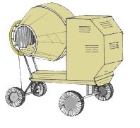 |
Mini-mixer (electric)
 |
Grinding mixer (petrol or electric)
 |
31. Before preparing a concrete batch, gather all the ingredients required close to the mixer. Then proceed as follows.
(a) Pour 10 percent of the water
required in the drum.
(b) Add half of the coarse
aggregates, gravel and/or stones.
(c) Start mixing.
(d) Add all the cement required for
the batch.
(e) Wait for 30 seconds.
(f) Add all the sand required.
(g) Add the rest of the water.
(h) Add the rest of the coarse
aggregates.
(i) Mix for 4 minutes.
(j) Check the consistency and
correct it if necessary (see paragraph 32 in this section).
Note: when mixing concrete by hand or machine:
|
|
|
|
32. Good fresh concrete should have a plastic consistency. If this is not the case, its consistency should be corrected as follows:
|
|
33. Take note of the amounts of the materials added so that you will have the corrected proportions for the next batch of concrete.
34. For larger construction works or where the strength is critical, the quality of fresh concrete should be routinely tested before-use. This can be simply done using the slump test, which provides a relative measurement of the fresh concrete plasticity and its expected strength after setting or hardening.
35. To execute the slump test, you will need:
 |
 |
 |
36. Proceed as follows, using freshly mixed concrete.
|
(a) Wet the bucket and the base plate.
|
(b) Fill the bucket with the concrete to be tested, by placing it in layers of about 10 cm.
|
|
|
(c) Use the wooden rod to pack each layer thoroughly before filling the next layer. |
||
|
(d) Smooth the surface of the concrete to enable you to fill the bucket exactly to the top.
|
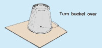
(e) Carefully turn the bucket upside down on to the base plate. |
|
| (f) Carefully lift the bucket off the
concrete, place it alongside and immediately measure, in cm, the difference
between the height of the slump cone and the height of the bucket (original
concrete cone).
(g) This difference is called the slump. |
 |
37. Compare the measured slump with the range of values suggested according to the type of construction (see Table 11). Usually, a slump of 25 to 30 percent should be taken as satisfactory. Note that with some standard mixes, the concrete may shear. If so, repeat the test, or estimate the slump from the upper edge of the remaining sample.
|
TABLE 11
* Expressed as percentage of bucket height at 30°C |
38. If the slump is not satisfactory, the cement quality has
to be improved using the same proportions as in the original mix as follows:
|
 |
39. Concrete is usually used in conjunction with forms (shutterings), which determine the final shape of the concrete structure to be built. In many cases the concrete is reinforced (see Section 3.5).
40. The forms in which the concrete can be cast are generally made of light, cheap wooden boards and timber pieces, nailed or bolted together. For a series of standard shapes, steel plate is sometimes used.
41. Good forms should have the following characteristics. They should:
42. Forms should be well braced so that they remain firmly in place.
|
A form for a concrete wall has two sides
 |
Form ready for placing concrete
 |
43. Concrete should be as fresh as possible when placed, ideally:
44. Once the concrete has started to set, it cannot be used. It is therefore important to have everything ready for use. Only make as much concrete in each batch as you can place in the time available.
| 45. Avoid placing concrete under water, because it is very difficult to make good concrete in these conditions. Use a drainage ditch, if necessary, to make sure that the concreting site is well drained. The earth, however, should be slightly moist. The supporting base should be firm and in many cases may require a layer of rock, brick rubble or other aggregate. If the concrete is to be firmly placed on rock, it should be well cleaned and dried. |
Placing concrete
 |
|
|
A foundation site
 |
A general building site
 |
46. Avoid segregating the ingredients of the concrete during placing, as this weakens the concrete and makes poor surfaces and poor joints between layers:
|
 |
|
| 47. Before placing the concrete in the forms, you should
oil or grease their inside surface to make it easy to remove them
once the concrete has set. You should also wet the forms.
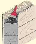
48. Place concrete in layers 15 to 20 cm thick. The concrete should be strongly rammed to tighten the coarse aggregates and should have a 2 to 3-cm "soft" upper surface to ensure a strong liaison with the next layer. |
 |
|
|
49. Use a shovel, a wooden pole or a 2-cm diameter iron rod to tamp the fresh concrete firmly into place.
|
50. Do not try to use "wet" concrete to make better joints, as it will only separate more and the water will wash out, leaving a very poor surface and joint. |
|
| 51. You can also hammer on the outside of the forms to help
to settle the concrete along the sides.
52. If the previous layer has set, roughen its upper surface to make a good connection to the next layer. You can also brush on a coat of liquid cement, which is cement dissolved in water. If available, use a cement bonding compound instead. |
 |
|
|
Roughen the surface
 |
||
|
Coat with liquid cement or bonding compound
 |
Note: it is always best to build a structure continuously, without interrupting the placing of the concrete. Remember the higher the structure, the stronger the forms have to be. If this is a problem, it may be necessary to build the structure in stages, letting each stage set before placing the new stage.
53. Within less than half an hour after adding water to the cement, the chemical reaction between these two ingredients results in the setting and progressive hardening of the concrete. The concrete acquires its strength, durability and impermeability during the curing process. To get the strongest possible concrete, curing should not be too rapid. It normally takes at least 28 days.
54. If the concrete is allowed to dry out, it will stop hardening; the curing process will not start again when the concrete is rewetted. Therefore, as soon as the concrete is placed, you should protect it from drying too fast by following these guidelines.
(a) Do not let the concrete dry out before placing it.
(b) Avoid placing concrete during the hot hours of the day.
(c) Wet the forms abundantly before placing the concrete. Keep them wet and do not remove them too quickly.
 |
 |
(d) Protect concrete from sun and wind, covering it with wet burlap, canvas, empty cement sacks, palm leaves, banana leaves, damp sand.
(e) Keep these covers wet so that they do not absorb water from the concrete.
(f) Sprinkle the concrete regularly with water after it has hardened enough not to wash out.
 |
 |
55. Keep the concrete from drying out:
56. It is best not to remove the forms from the concrete until the curing process has progressed well for at least 48 hours. In some cases, it may take as long as 21 days before the forms can be totally removed. When the forms have been removed, clean up any rough surfaces and fill any larger gaps or holes with mortar, if necessary.
57. You can make simple concrete blocks using a standard wooden
form, which can be reused (see section 3.2 for standard block sizes). A
mix of 1:2:4 to 1:5:8 can be used, with aggregates smaller than 13 mm across
and a fairly moist mix. You will need to cure the blocks carefully as they will
split and break if handled too soon or left to dry out. Normally, the finish
is not as good as that for machine-made blocks, which are formed under pressure
using a dry concrete mix.
Note: the forms shown on this page are for blocks of 20 x 20 x 40
cm.
|
A simple box form for making a solid block
 |
A two-piece form for making a hollow block
 |
Push-out form |
Details for building the outer form and the inner mould for making a hollow block
|
Outer form
 |
Inner form
 |
|
When the cement is nearly dry, carefully remove
the inner form and slowly push the block from the outer |
1. Reinforced concrete is made by adding reinforcement to normal concrete. Reinforcement is used to keep the concrete from collapsing.
Selecting reinforcement |
||
|
2. There are three main kinds of concrete reinforcement:
|
Round steel bars
 |
|
|
Expanded metal mesh
 |
||
3. To use reinforcement, you may also need:
|
Welded wire mesh
 |
|
4. The amount of reinforcement needed for a particular construction should be determined by an engineer, who should also specify how and where the reinforcement should be placed within the concrete to avoid collapse. Simple specific designs are given in the second part of the manual.
5. For your guidance only, the number of steel bars is generally calculated as a percentage of the gross area of each section of concrete as follows:
|
Area of steel (in mm2)
present in concrete section according to diameter and number of steel
bars*
* For round and smooth steel bars |
|||||||||||||||||||||||||||||||||||||||||||||||||||||||||||||||||||||||||||||||||||||||||||||||||||||||||||||||||||||||||||||||||||||||||||||||||||||||||||||||||||||||||||||||||||||||||||||||||||||||||||||||||||||||||||||||||||||||||||||||||||||||||||||||||||||||||||||||||||||||||||||||||||||||||||||||||||||
Example:
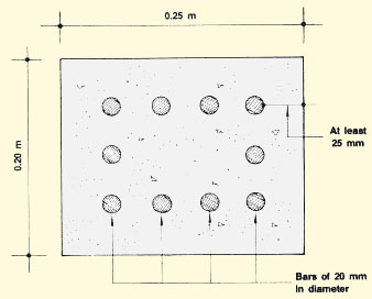
A reinforced concrete column 0.20 x 0.25 m is to be built. The necessary
reinforcement can be estimated as follows:
(a) Calculate the gross area of the section of the column: 0.20 m x 0.25 m = 0.05 m2 = 500 cm2
(b) Calculate the minimum area of the steel reinforcement required: 500 cm2 x 0.06 = 30 cm2 = 3000 mm2
If you plan to use 10 steel bars as shown in the drawing, start with the 10-bar column on the right-hand side of the chart above. Follow the column down until you find an area at least equal to 3 000 mm2 or in this case 3 141 mm2 . Now follow this line across and you will see that this area corresponds to a steel bar diameter of 20 mm. So, for this size of concrete column use reinforcement made of 10 steel bars of 20 mm.
 |
6. The steel bars should be clean and free of oil and earth. Rust, unless so severe that bars are weakened, does not require particular attention, although any loose rust should be removed with a wire brush.
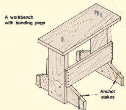
7. To bend the steel bars according to design, you need a well-fixed piece of steel plate or heavy planking in which you have driven or fixed four small pegs of 10-mm diameter steel bar. If you plan to bend a lot of bars, you may prefer to build a strong workbench.
8. Buy a special clamp or make one yourself by sawing a narrow notch in a piece of very thick steel bar or rod.
9. Insert the steel bar to be bent between two of the first three pegs, making sure that the bar is positioned to bend in the right place. Using the clamp, bend the steel bar at the level of the single peg.
10. Once the steel bars have been cut and bent according to design, the reinforcement is constructed. The bars should be firmly and securely bound together at their intersections with tie wire (see paragraph 3 above).
 |
 |
|
 |
 |
11. By using wire mesh reinforcement, you can make simple slabs with a fairly moist concrete mix of 1:2:4 to 1:5:8 that has aggregates smaller than 13 mm across. To make a slab, place the concrete inside a simple wooden form resting on a flat surface or level a piece of ground, cover it with a heavy plastic sheet and put the wooden form on that. As with blocks, you should take care in curing the concrete.
Note: the wire mesh may be held in place within the form using strips of wood over the top of the form and hang wires (see below). Remember to leave at least 25 mm of free space all around the mesh and between the top and bottom of the form. Also, it is often useful to set in one or more small loops to use as handles for lifting or moving the finished slab.
|
A reinforced concrete slab
 |
Compact concrete
 |
|
Detailed section through form with concrete in
place
 |
Note: the form shown is for a slab of 7 x 50 x 100 cm. However, dimensions may vary from 5 -10 x 30 - 80 x 50 -120 cm
Making reinforced concrete |
||
|
12. To reinforce concrete, proceed as follows. (a) Fix the reinforcement well, exactly according to the engineering design, There should normally be at least 25 mm between the bars and the outside surface. Make sure tie wires are sound, and that the bars are not twisted. (b) Place the forms around the reinforcement. If necessary, use spacers to hold reinforcement bars in place. |
A reinforced concrete column
 |
(c) Wet the form and the reinforcement well.
(d) Place the concrete into the form, without disturbing the reinforcement.
(e) Compact the concrete well, especially around the reinforcement, but do not disturb the reinforcement or shake it.
|
Wet form and reinforcement
 |
Place concrete
 |
 |
|
(f) Take particular care in making good joints between layers.
|
(g) Cure the concrete well before
removing the form.
(h) Remove any spacers if used, and finish and fill the outer surfaces. Be careful to make sure no reinforcement is exposed to water.
|
1. There are several other materials commonly used for construction purposes, particularly where supplies for normal cement or concrete are not easily available. These are generally not so strong or durable, but may be used if necessary. There are also many specialized materials, but these are usually too expensive or too complex to use for most fish culture constructions. Some of the materials you might use are:
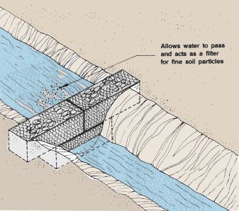
1. A gabion is a wire mesh cage or basket filled with stones. Gabions are useful in construction works, for example to protect earth embankments, to line channels, to manage or divert river or stream flow and to protect river banks or coastlines.
2. You can buy wire mesh baskets and make your own gabions. The standard gabion basket consists of a single piece of wire mesh that can be assembled to form a rectangular box with a lid.
|
Stone-filled gabion
 |
Galvanized wire mesh ready to be assembled
 |
Wire mesh basket assembled
 |
3. Wire mesh baskets for gabions can usually be found in two standard sizes. They are for:
4. The width of a standard basket is usually 1 m, and the length varies from 2 to 5 m or more.
|
Standard gabion
 |
Half-height gabion
 |
|
| 5. Galvanized steel wire is used for making baskets for gabions. The wire is usually 3 mm in diameter and is twisted to form a mesh opening from 100 to 120 mm wide. Both single and double twist mesh are available, although double twist is better. |
 |
6. Gabions have a number of important advantages in construction:
|
Shape easily adapted
 |
A three-gabion barrage
 |
7. Gabion structures normally consist of two parts:
|
 |
|
 |
 |
|
| 8. Half-height gabions may also be placed
on sloping river or stream banks or terraces. The gabions must be well
supported at their base.
9. For most fish farm uses, structures are not more than two or three gabions in height. Along stream banks or channels, a single gabion width is usually adequate. Structures two or three gabions or more in width may be needed for stream diversions in rapidly flowing water. Normally, the slope of gabion structures is from 45° to near vertical. |
River or stream banks
 |
|
River or stream diversion
 |
|
River, stream or channel banks
45° bank  |
30° bank
 |
Nearly vertical bank
 |
10. Wire mesh baskets are built one at a time, put in place according to the design of the structure and then filled with stones. The following steps will tell you what to do.
| (a) Begin the first basket by unfolding a section of wire mesh and stretching it out flat on the ground. |
(b) Fold the front, back and sides to form a box with the lid open. |
|
| (c) Securely wire the four corners of the mesh box together
as shown. This should be done very carefully using galvanized steel wire
of the same quality and diameter as the mesh wire. Do not pull the wire
with pliers, because you may tear and weaken the box.
|
 |
|
|
(d) After you have wired the four corners together, carry the basket to where you will use it.
|
(e) When a basket is in position, make sure that it is straight and square. To do this, stretch the front, back and side, driving a 1.5-m iron bar into each corner as shown. As each corner becomes straight and square, drive the bar into the ground to hold it in place. |
|
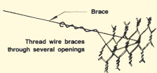
| 11. Each mesh basket must also have extra wire
bracing to help support the weight of the stones when the basket
is filled. As braces, you can use the same wire you used to secure the
four corners of the box.
12. The vertical braces are attached as soon as the basket is in place. The horizontal and angle braces are added as the baskets are filled with stones. 13. The drawings show you where to put vertical, horizontal and angle braces, both for a full-height gabion and for a half-height gabion. |
Braces for full-height gabion - 1 x 1 x 5 m Braces for half-height gabion - 0.5 x 1 x 5 m |
|
14. Each brace is attached by threading it through several of the wire mesh openings.
|
|
|
| 15. Now you are ready to start filling the basket with stones.
16. A foundation basket is best filled with round or rounded stones at least one-and-a-half times as large as the openings in the wire mesh. Avoid using stones larger than this. If the stones are too large, you cannot easily deform the basket to fit irregular or curved sites such as stream banks. Note: try to choose stones that fit closely together so that there will be no large empty spaces in the basket. |
 |
|
| 17. A structure basket is also best filled with stones, at least one-and-a-half times as large as the openings in the wire mesh. However, if you do not have enough large stones, you can use smaller stones in the centre of the basket if they are at least 8 cm in diameter. If you use smaller stones, first line the bottom and sides with large stones, then fill the centre with smaller stones and finally cover the top with a layer of large stones. |
 |
|
18. When you are filling baskets with stones, make sure that the vertical wire braces stay vertical.
|
19. Attach the horizontal braces and angle braces from time to time as you put in the stones. |
Note: use hard stones such as granites, quartzites, sandstones, laterite and hard calcareous stones for filling baskets. Do not use schists, gneiss or serpentine, which are too friable, may break down in strong water currents and may eventually wash out of the baskets causing them to collapse.
20. When the basket is filled with stones, you can remove the iron bars from each corner.
21. Close the lid of the basket, pull the edges tight and fasten them every 20 cm with galvanized steel wire, using a short piece of iron for a lever as shown.
 |
 |
|
| 22. Finish the basket by attaching the vertical braces to the lid. |
 |
23. After the first basket is in place and filled, add empty baskets one by one according to the design of the gabion structure.
(a) Wire the back and sides of each new basket to the filled baskets already in position.
(b) Stretch the front corners of each empty basket using a 1.5-m iron bar until the basket is straight and square. Then hold it in place by driving the iron bar into the ground or into the gabion below.
(c) Attach the braces and fill the basket with stones as before. Remove the iron bars. Fasten the lid and attach the vertical braces.
24. Continue to add more empty baskets until the gabion structure is finished.
 |
 |
|
 |
1. Pipes are widely used on fish farms to transport water, for example through dams and dikes or under roads.
2. The type of pipe to be used depends on the size or diameter required for the planned water discharge capacity:
3. Generally, concrete and ceramic pipes are cheaper for a given size, but cannot be made in small sizes.
Selecting concrete pipes |
||
|
4. There are three types of concrete pipe. In order of increasing strength, they are:
5. Unreinforced concrete pipes are usually precast, with a standard length of 1 m. They are connected by a joint sealed with cement mortar. Their diameter should be limited to a maximum of 50 cm. It is best to lay them under ground, at least 50 cm deep. 6. Reinforced concrete pipes are rarely used in fish farming, perhaps only when very large diameters are needed.
|
Examples of concrete pipe
 |
|
| 7. Asbestos-cement pipes are made by adding asbestos fibres to the concrete to increase strength. These pipes are more costly but have the advantage of being lighter, stronger and available in longer standard lengths (3 to 6 m). This reduces the number of joints to be sealed with cement mortar. The inside diameter usually varies from 15 to 30 cm. The pipes are laid down in a trench deep enough to protect them with at least 50 cm of soil. The foundation supporting them should be carefully built to accommodate the reinforced collars of the pipes. |
Examples of asbestos - cement pipe
 |
|
Selecting ceramic pipes |
||
| 8. Ceramic pipes are made of baked clays, usually with a hard glazed exterior finish, with typical diameters of 10 to 20 cm. They are normally in short lengths, 50 cm to 80 cm, with a collar fitting at one end, sealed with mortar. Ceramic pipes are not strong and are easily broken in handling. As with plain concrete pipes, they must be well protected under ground. |
Enlarged example of ceramic pipe
 |
|
9. For smaller water flows, galvanized iron pipes (inside diameter 5 or 6 cm) or plastic pipes are normally preferred. The standard lengths available are usually longer (3 to 6 m), which reduces or may even eliminate the need for joints.
| 10. For plastic pipes, pressure pipes are stronger, heavier, and more expensive than drainage pipes. They are suitable for higher water pressures, for example pumped water supplies, and wall thickness depend on the pressure rating needed. Drainage pipes are lighter, have thinner walls, are cheaper and are suitable for low pressure, for example pond drains. The example below shows a drainage pipe with a flexible "o" ring inset in the collar for a "push fit joint". |
 |
|
|
Enlarged example of plastic drainage pipe showing
detail of collar with flexible "o" ring
 |
||
11. It is best to protect plastic pipes from the sunlight, as they can become brittle if kept exposed.
12. To select the correct size of pipes to be used on your fish farm, for example at the inlet and outlet of fish ponds, you should first know which water discharge is required in each case. You should then determine which size of pipe will have the capacity for such water discharge. Finally, it is best to standardize the pipes and to select only a limited number of different sizes.
13. The water discharge capacity of a pipe increases with the pressure head (measured in cm) at the entrance of the pipe (see Section 3.7,Water,4). This is also shown in Table 12 for pipes of different sizes.
|
TABLE 12
|
|||||||||||||||||||||||||||||||||||||||||||||||
14. Very often, the pressure head varies, for example on the outlet pipe as the fish pond is being drained. It is best, therefore, to estimate the capacity of the pipes by one of the following simple methods.
(a) Using Table 13 and Graph 1, you can estimate the water discharge
capacity of pond outlet pipes of various diameters.
(b) Using Table 14, you can estimate the pipe sizes
required to drain a pond of a particular size in a specified time.
(c) You can use mathematical formulae to estimate:
|
Q = 0.078 D2. |
so, for a pipe with D = 20 cm,Q = 0.078 x 202 = 31.2 l/s;
|
D = 3.56 ÖQ |
so, for Q = 16 l/s, you require a pipe with D = 3.56 Ö16 = 3.56 x 4 =14.2 cm; and you will probably use a 15-cm pipe.
Note: all of these methods assume you are using a simple, short pipe with no obstructions to water flow, such as complicated sluice gate assemblies, screens, dirt or fouling inside the pipe's internal edges, or lips or edges at the mouth or joints of the pipe. Any of these will reduce the flow. If you have or expect to have any obstructions in the pipe, use a larger size. If the pipe is made up of several sections of different diameters, estimate the water flow on the basis of the smallest diameter pipe you use.
|
TABLE
13
* Based on a pressure head of about 15 cm |
TABLE 14
Note: these figures assume an initial internal water depth of 1 m, with pipe velocity limited to 1 m/s; for two pipes, etc., time is divided by 2 |
|||||||||||||||||||||||||||||||||||||||||||||||||||||||||||||||||||||||||||||||||||||||||||
15. To design a pipeline, you have to use a different method to determine its water discharge capacity, taking into account its length and the head loss* from start to end. In addition, you should check that the water velocity in the pipeline will not exceed a critical value. Proceed as follows.
(a) Select a pipeline inside diameter and calculate its water discharge capacity (in l/s) as:
|
Q = KÖ(H ÷ L) |
where K is the conveyance factor (in l/s), see
Table 15;
H
is the head loss (in m) over the pipeline length;
L
is the total length (in m) of the pipeline.
Example
A concrete pipeline has an inside diameter of 20 cm. It is 100 m long (L), and its total head loss (H) is 2 m. Its water discharge capacity is: Q= 399.7 l/s Ö(2 ÷ 100) = 399.7 Ö 0.02 = 56.53 l/s
|
A 100-m concrete pipeline with a straight run
|
(b) Calculate the water velocity V (in metres per second, m/s) in the given pipeline as:
|
V = M Ö(H ÷ L) |
where M is the velocity modulus (in m/s), seeTable
15;
H is
the head loss (in m) over the pipeline length;
L is
the total length (in m) of the pipeline.
Example
Using the same concrete pipeline with an inside diameter of 20 cm, a length (L) of 100 m and a total head loss (H) of 2 m, the water velocity is: V = 12.729 m/s Ö0.02 = 12.729 x 0.141 = 1.79 m/s
(c) Compare the calculated water velocity V (in m/s) with the corresponding maximum velocity recommended in the last column of Table 15.
Example
Using the same example, the calculated water velocity V= 1.79 m/s exceeds the maximum recommended velocity Vmax = 0.90 m/s. Total head loss should be reduced.
|
TABLE 15
Note: M and K are constants |
||||||||||||||||||||||||||||||||||||||||||||||||||||||||||||||||||||||||||||||||||||||||||||||
16. The formulae you have just used are suitable for straight pipes, but the flow of water is reduced by bends on the pipe or any fittings. The simplest way to allow for these is to think of each bend or fitting as being equivalent to an extra length of pipe of an equivalent length. Table 16 shows equivalent lengths for typical fittings.
Example
If the pipe used previously (20-cm diameter and 100 m long) has four 90° bends, two check valves (fully open) and a reducer outlet, its discharge capacity is still: Q = 399.7 ÖH ÷ L
L is now the total equivalent length (TEL)
or the length of the pipe plus the equivalent lengths of the fittings.
Thus TEL = 100 m + equivalent lengths (in m) of four 90° bends
+ 2 check valves + reducer outlet
= 100 m + 4(0.4D) + 2(0.75D) + (0.08 D).
For the pipe diameter D = 20 cm,TEL = 100 m + 4(0.4 x 20) m + 2(0.75 x 20) m + (0.08 x 20) m =163.6 m.
Then Q = 399.7 Ö2 ÷ 163.6 = 44.19 l/s, which is less than 80 percent of the flow of the straight pipe, as calculated in the previous example.
|
TABLE 16
Note: these are typical values and may vary
according to design and manufacture |
|
A 100-m concrete pipeline with four 90° bends
|
1. If you intend to use a pump, you will need to know the right size or power P (in kW) of the pump for the job. You need to consider the head H(in m), the water flow Q (in m3/s) and the efficiency E (in percent) of the pump. You can use a simple equation such as:
|
P (kW) = (9.81 x Q x H) ÷ E |
where the pumping head H (m) is calculated as the sum of the suction head (hs), delivery head (hd) and pipe loss head (hp).
(a) For the commonly used field pumps, the suction
head (hs) should be kept as small as
possible. Most suction heads will not draw up more than 3 to 5 m in field use.
(b) The delivery head (hd)
is generally in the range of 2 to 10 m.
(c) The pipe loss head (hp) can
be calculated from the formula used in Section 3.8, Q = KÖhp
÷ L, and therefore:
hp = LQ2
÷ K2
where Q is the known water discharge (in l/s);
L
(or TEL) is the total length (or total equivalent length)
of the pipeline (in m);
K
is the conveyance factor (in l/s), see Table 15;
hp
is the pipe loss head (in m).
|
The definition of suction head (hs)
and delivery head (hd)
 |
 |
|
|
Note: hs=distance from lower water level to
pump centre line |
2. With simple, short lengths of pipe of at least the same size as the pump inlets and outlets, the pipe loss head can be ignored.
Example
Using a pump of 60 percent efficiency in the middle of the pipe system
described earlier, where TEL = 163.6 m, the flow rate Q
= 80 l/s, the suction head (hs) = 1 m and the delivery
head (hd) = 2 m, the power required is: P(kW)
= (9.81 x Q x H) ÷ E.
Calculated total head H is 1 m + 2 m + pipe head loss (hp),
where hp = LQ2 ÷ K2
= [163.6 m x (80 l/s)2] ÷ (399.7 l/s)2
= 6.55 m.
Thus total head H = 1 m + 2 m + 6.55 m = 9.55 m.
3.Table 17 shows the power (in kW) required for various rates of flow (m3/s) and total heads (m), assuming a typical pump efficiency of 60 percent (the usual range is 40 to 75 percent). To convert these to horsepower (HP), divide the kW value by 0.75.
4. In some cases, pumps are defined by the diameter of their outlet pipes, usually expressed in inches. Then you can tell whether a certain pump is sufficient for your needs, by estimating its horsepower as
|
HP = 3.14 D2 ÷ 20 |
where D is the inside diameter of the outlet pipes in inches.
Note: one inch is equal to 2.54 cm.
5. If the pump is to be run for long periods of time, you should increase the power by at least 30 percent, as most pumps should not be run fully loaded for too long. The power of the motor should be at least 10 percent more than the pump power.
Example
Pump power required (based on previous example):
P = (9.81 x 0.08 m3/s x 9.55 m) ÷ 0.60 =
12.5 kW
or 12.5 kW ÷ 0.75 =16.7 HP
Select a 20 HP pump with for example a 25 HP motor. But if this is to be run for long periods, a pump of 26 to 30 HP would be needed, with a 30 to 35 HP motor.
| 6. In many cases, you can select a pump using information provided by manufacturers or dealers. This is often provided as a head-output curve (see Graph 2), which shows the pumping ability of each type of pump. |
|
TABLE 17
* To convert these kW values to horsepower, divide them by 0.75 |
|||||||||||||||||||||||||||||||||||||||||||||||||||||||||||||||||||||||||||||||||||||||||||||||||||||||||||||||||||||||||||||||||
7. If you have a choice, try to use the pump which is the most efficient for the work, as this reduces running costs. Efficiency is often shown on the same head-output curve or can be estimated. The pump usually works most efficiently at around 60 to 70 percent of its maximum head or output.
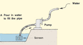
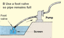
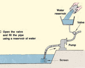
8. Most general-purpose field water pumps are suitable for fish farms, although if the water is brackish or carries a lot of mud, you should check that the pump is suitable. You should fit a screen at the pump intake. For centrifugal pumps (the most common type), a foot valve is useful for keeping water in the pipe when the pump is stopped. The pipe is filled with water (primed) before starting, as the pump cannot suck the water into the pipe by itself.
|
Several ways to start centrifugal pumps
 |
 |
 |
9. If a pump is already available, and you do not know its dist as follows.
(a) Estimate its horsepower HP from the outlet
pipe inside diameter (D in inches), as HP
= 3.14 D2 ÷ 20.
(b) Multiply HP by 0.75 to obtain the pump power
P in kilowatts.
(c) Check its maximum head H (in m) by running the pump
and lifting the outlet pipe until the flow stops. The pump can usually operate
in the range of 30 to 70 percent of this maximum head.
(d) Estimate the discharge capacity Q (in m3/s)
from values of power (P) and head (H), as
|
Q = (PE) ÷ (9.81 H) |
where E is the pump efficiency in percent.
Example
If a pump has an outlet pipe diameter of 3 inches (7.5 cm):
HP is approximately = 3.14 D 2 ÷ 20 = 1.4 HP.
Pump power, kW = 1.4 x 0.75 = 1.1 kW.
If maximum head = 8 m, efficient working head is usually from 30 to 70 percent, i.e. about 2.5 to 5.5 m.
Discharge capacity, for example at 4 m, assuming a 70 percent efficiency,
is
Q = (PE) ÷ (9.81 H) = (1.1 x 0.7) ÷ (9.81 x 4) = 0.77÷ 39.24
= 0.02 m3/s = 20 l/s.
10. You can also check the discharge capacity of the pump Q (m3/s) by measuring how long it takes to drain or fill a known volume of water. By estimating the total head, you can work out the pump power.
Example
If a pump fills a 50-litre barrel in 10 seconds, with an estimated total head of 10 m, efficiency is estimated at 30 percent as the pump is near its maximum head (found to be 12 m). Q (m3/s) = volume/time 0.05 m3 ÷ 10 s = 0.005 m3/s.
![]()