12. SOILS AND FRESHWATER FISH CULTURE
12.0 What have you learned?
In the previous chapters of this manual you have been told:
- How soils develop with time;
- What the main soil characteristics are;
- How to evaluate these soil characteristics so that you can use this information to your advantage.
On the basis of this new knowledge, you should be better able to:
- Select a suitable site for either small reservoirs or freshwater fish-ponds;
- Manage your ponds.
Site selection and pond management will be discussed in detail in later volumes of Simple methods for aquaculture, but certain aspects will be briefly discussed here so that you will have an idea of how the results of your soil survey may apply directly to these two subject areas.
12.1 Soil suitability for the building of earthen ponds
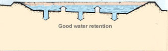
If you plan to build earthen fish-ponds, soil quality will be important, both for the selection of the best materials for making the pond dikes and for designing the fish-farm. The inlet canals and the pond bottoms will have to be sufficiently impermeable to minimize water losses by seepage. For good fish production, the fertility of your pond water should be maintained to prevent the loss of nutrients through high permeability of the pond bottom.
Note:the coefficient of permeability of soils to be used for pond bottoms should preferably be smaller than
K = 5 x 10⁻⁶ m/s.
When a site is unsuitable for earthen ponds
A site may be considered unsuitable for earthen ponds if it contains:
- Rock outcroppings or big surface stones;
- Gravel beds or rocky soils;
- Sandstone soils;
- Organic soils such as peat soils which should be avoided if possible because of their fast permeability and their unsuitability as dike construction material. When ponds are built in such soils, special construction techniques will have to be used.
When a site is suitable for earthen pondsA site may be considered suitable for earthen ponds if the soil will ensure:
To be suitable, the texture of the soil should be fine grained with the silt and clay particles representing more than 50 percent of the total dry weight. The best soils for fish culture are the sandy clay, silty clay loam or clay loam soils which belong to the USC-CL group. |
Good pond fertility
 |
Dam or pond dikes
The suitability of a soil as material for building a dam or pond dikes decreases as the percentage of the clay particles decreases. This can be seen from Table 25 where soils with different textures are compared for permeability, compressibility and compaction characteristics.
The characteristics of different soil materials for compacted embankments are summarized, for guidance only and according to USC soil groups, in Table 26. The best compaction characteristics are achieved with soils having a liquid limit equal to 35 percent and a plasticity index equal to 16 percent. The moisture content of the soil should also be as close as possible to the optimum value (see Section 10.2).
Dikes without a clay core
For the construction of dikes without a clay core, look for the following soil material properties:
- Particles with a diameter smaller than 0.1 mm, 20 to 70 percent;
- Particles with a diameter smaller than 0.05 mm, 10 to 40 percent;
- Plasticity index, 8 to 20 percent;
- Coefficient of permeability from 1 x 10⁻⁴ to 5 x 10⁻⁶ m/s.
Dikes with a clay core
For the construction of dikes with a clay core, you must use a good impermeable material for the clay core with the following plasticity characteristics:
- Liquid limit greater than 60 percent;
- Plastic limit greater than 20 percent;
- Plasticity index greater than 30 percent.
Note:the relative position of the particle-size frequency curve of your sample may also assist you in judging soil suitability, as discussed later in Section 12.4.
|
TABLE 26
Characteristics of various soil materials for the construction of dikes and dams1
1 This information given for
guidance only. |
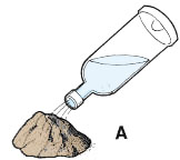
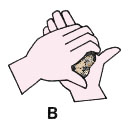
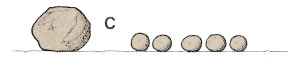
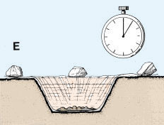
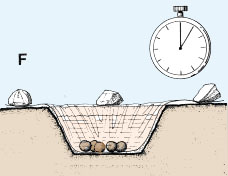
A simple test for soils to be used in building embankments
It is very important to know the ability of a soil to resist water saturation* when you are selecting soil material for embankment construction. Here is a very simple test that you can perform to determine this soil quality:
|
 |
|
|
 |
|
|
 |
|
|
 |
|
||
|
 |
|
|
 |
12.3 Soil suitability for water canals
The relative stability of various USC soil groups for water canals, such as inlet and outlet canals for fish-farms, varies, as shown in Table 27, which gives estimates of resistance to water erosion and of suitability as compacted earth lining. When digging water canals, you should also consider the permeability characteristics of the soil, giving preference to those with a coefficient of permeability smaller or equal to 10-5 m/s.
NOTE: Number 1 indicates the best soil |
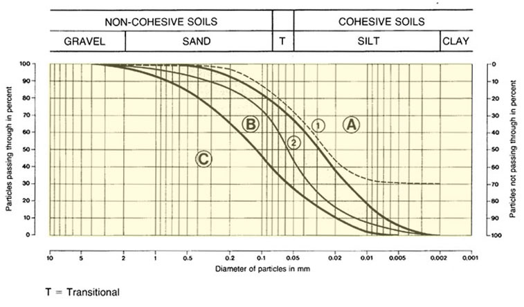
12.4 Determination of soil suitability with the PSF-curve
If you have the particle-size frequency curve for your soil (see Section 6.7), you may compare it with the particle-size frequency curve for your soil (see Section 6.7), you may compare it with reference curves and determine the relative suitability of the soil for pond construction or for building dikes. This method, however, is normally used only for the planning and design of relatively large fish-farms by technicians specialized in civil engineering. This is an example of how it is used:
- You have taken a disturbed soil sample from the B-horizon of one of your soil profiles to the testing laboratory. It has been analysed for a series of particle sizes and the results have been given to you, either as percentages of occurrence by weight or as a particle-size frequency curve;
- If you have the results as percentages of occurrence, plot this information in pencil on a photocopy of the graph given in Table 28 and trace your sample PSF- curve;
- Now compare your PSF-curve with the two reference curves on the graph ...
- If your sample curve falls within Zone A, the soil is suitable for a pond bottom, providing that its coefficient of permeability K is less than 5 x 10⁻⁶ m/s (see Table 16);
- If your sample curve falls within Zone B, the soil is suitable for building dikes without an impermeable clay core;
- If your sample curve falls within Zone C, you will require further studies concerning the soil characteristics (see Sections 12.1 and 12.2). You may find that the soil may be used but only under particular conditions such as, for example, by puddling the pond bottom and using an impermeable clay core in the dikes.
Note: before making a final decision on the suitability of your soil, you should carefully check the other important soil characteristics such as soil structure and permeability. These should confirm your diagnosis (see Tables 17A and 17B).
Examples
- Two soil horizons have been sampled in an open pit and mechanical analyses in the laboratory have provided particle-size frequencies;
- Cumulative frequencies are calculated;
|
||||||||||||||||||||||||||||||||||||||||||||
|
||||||||||||||||||||||||||||||||||||||||||||||||
- The PSF-curves are plotted on a photocopy of the reference graph given in Table 28, using the right vertical scale to plot the cumulative frequencies;
- Compare the position of the sample curves with the position of the reference curves ...
- Sample 1 is a clay loam with 28 percent sand, 42 percent silt and 30 percent clay and its PSF-curve falls within Zone A of the reference graph, which suggests that this is a suitable soil for use as a pond bottom;
- Sample 2 is a sandy loam with 56 percent sand, 43 percent silt and 1 percent clay and its PSF-curve falls within Zone B, which suggests that this is a suitable soil for the construction of pond dikes without an impermeable clay core.
12.5 Soils and pond managementA soil survey will help you to plan and practice better pond management by reducing seepage losses and by improving pond fertility. Reduction of water losses by seepage |
||
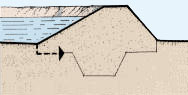
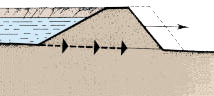
| If the pond has a sandy bottom soil, the seepage will be unusually high, 10 cm per day or more, and particularly during the first year after construction. To reduce seepage, you can block the soil pores by spreading organic matter such as compost and animal manure on the pond bottom and mixing it well with the top 10-15 cm of soil. |
 |
|
If the soil of the pond bottom has a strongly developed structure and high seepage losses, 10 cm per day or more, it may also be necessary to destroy the structure either through mechanical compaction, using a crawler tractor or a sheeps-foot roller, or through puddling . If the percentage of clay present in the pond bottom is high, more than 60 percent, when draining the pond you should not allow the pond bottom to become too dry. If this happens, deep cracks may develop and this may increase seepage losses later when you refill the pond. |
 |
 |
 |
Improvement of pond fertility
If the pond bottom is acid, with a low pH, you can improve pond fertility by adding lime to neutralize the acidity. This is a technique which will be discussed further in a later volume of Simple methods for aquaculture.