11. FLOOD AND SILT CONTROL STRUCTURES
11.0 Introduction
1. Your fish farm should be protected against four major causes of fish production losses:
- excessive water supply;
- uncontrolled surface runoff;
- silty water; and
- fast running water.
2. Any excess water entering a full fish pond, such as flood water or runoff water, should be immediately and automatically discharged. Depending on the amount of water to be carried away, you can use the pond outlet itself, or additional structures such as pipe overflows, mechanical spillways and emergency spillways. You will learn more about each of these in Sections 11.1 to 11.4.
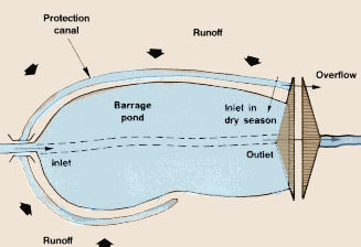
3. During heavy rains, the amount of surface runoff may become excessive, particularly for barrage ponds or ponds built at the bottom of large sloping areas with little vegetation cover. The runoff water in such cases is also often heavily loaded with fine soil particles that make it very turbid. If the runoff passes across cultivated areas it might accumulate toxic substances such as pesticides. To avoid such water reaching your fish farm, you will have to protect it with one or more protection canals (discussed in Section 11.5).
4. In certain regions, soil conditions are such that the water available for fish farming is very turbid, particularly during the rainy season. To clear such water and improve its quality, you can build a filter pond or a settling basin (discussed in Section 11.6).
11.1 How to discharge excess water from ponds
1. Excess water should be automatically and safely carried away from a pond. If it is not, the water level in the pond may rise above the maximum designed level and even reach over the top of the dikes. Significant damage may then occur, often leading to the destruction of the dike and the loss of fish.
2. In an earlier manual in this series, Water, 4, you learned about the various sources of water and the different factors that control their availability. You learned how the rainfall and the physical characteristics of the catchment basin (such as size, slope, soil and vegetation) determine the amounts of water that will reach your fish farm through various ways (such as runoff, groundwater, spring or stream water). Some of this water can exceed your pond requirements. In this case, you will have to discharge it away from your pond.
3. The amount of excess water to be discharged varies according to the type of pond:
- in diversion ponds, where the water inflow is regulated through the pond inlet, the need to discharge excess water arises only rarely if the inflow structure and the pond are well cared for;
- in sunk-in ponds and in barrage ponds with a diversion canal, the quantity of excess water is also usually limited except in very large ponds (1 to 2 ha or more) during heavy rains, when runoff may increase considerably and may converge into the pond;
- in barrage ponds without a diversion canal, the discharge of excess water may vary in size, may be permanent or seasonal, according to the natural flow regime of the feeding stream; it can become exceptionally high during floods.
4. You may find, in checking through this section, that the cost of these overflow and protection structures is high enough to justify either:
- installing a diversion canal (see Section 8.6); or
- using a different site.
5. There are different ways of discharging excess water from fish ponds:
(a) If your fish pond has a free-flowing outlet, such as a sluice gate or a monk, and if the amount of excess water to be discharged is always small enough, you do not need any other structure. To find out how much water you should be able to discharge through typical outlets, see:
- for sluice gates, Graph 6 and Tables 32 and 33 (Chapter 7); and
- for monk pipelines, Tables 12, 13 and 14 (Section 3.8).
If possible, it is often cheaper to provide a larger than normal pond outlet than to build an additional structure.
Note: remember to clean the outlet screens regularly so that the excess water can flow easily through them.
(b) If your pond has no free-flowing outlet or if your outlet is too small, and if the amount of excess water to be discharged is always limited, you can have a pipe overflow (see Section 11.2).
(c) If the discharge of excess water is relatively large and continuous for long periods of time, you should, in addition to any pond outlet, build a mechanical spillway (see Section 11.3).
(d) If the discharge of excess water becomes exceptional on certain occasions, you should, in addition to any pond outlet and any other discharging structure, build an emergency spillway (see Section 11.4).
6. To assist you in selecting the right type of structure to discharge any excess water from your ponds, consult Table 49.
11.2 The pipe overflow
1. To carry away a normal flow of excess water which is reasonably small, you can use a pipe overflow built in the upper part of a dike.
Choosing the correct type of pipe overflow |
|||||||||||||||||||||||||||||||||||||||||||||||||||
|
2. The number of pipes and their inside diameter should be selected according to the maximum water flow to be discharged. Usually, no more than two to three pipes are used side by side, and their individual diameter is limited to 15 to 20 cm. Estimate the water discharge capacity of pipes using the chart below to determine the type of pipe overflow you need. Note: whenever you use a pipeline to discharge excess water, remember that its capacity depends not only on its inside diameter, but also on the pressure head (see Table 12). |
Approximate water discharge capacity of overflow pipes
|
||||||||||||||||||||||||||||||||||||||||||||||||||
Building a pipe overflow
3. When building a pipe overflow remember the following:
(a) Place the overflow at one corner of the dike.
(b) Fix it well into the upper part of the dike.
(c) Make sure the pipe is long enough so that its overflowing end discharges the excess water beyond the toe of the dike to avoid eroding it.
(d) Alternatively, if the dike is firm, and you have the material, you can make a protected area, using coarse cobble and cement or a large piece of pipe cut to form a semi-circular channel, to take the water down the slope.
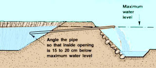
(e) Angle the pipe slightly so that:
- its inside opening lies at a level 15 to 20 cm below the maximum water level in the pond, to prevent floating debris from obstructing the pipe;
- its outside opening lies at the maximum water level and discharges any additional water.
Note: if you wish to remove cooler and deeper water from your pond, use an overflow that curves down at its inside end.
Selecting the type of pipe to use
4. Three types of pipe are most commonly used as overflows:
- bamboo pipes (see Section 3.1);
- galvanized iron pipes (see Section 3.8);
- plastic pipes (see Section 3.8).
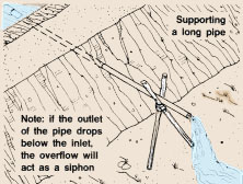
5. It is best to use one-piece pipes, avoiding any joints. If the pipe sags, or extends too far out from the outer side of the dike, it may be useful to put up some simple pipe supports, using for example wood or bamboo.
 |
 |
|
 |
||
 |
 |
|
 |
11.3 The mechanical spillway |
||
|
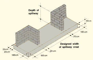
1. To regularly carry away a large flow of excess water, you should build an open structure, called a mechanical spillway, and its draining channel, the spillway channel. What is a mechanical spillway?2. A mechanical spillway consists of:
5. The grooves can be fitted with a board to roughly control crest height. The coarse screen helps to avoid fish losses, especially when a large quantity of excess water is to be spilled. However, if there is a risk of these blocking with excess debris, it may be better to install an additional, larger screen on the inside. In all cases, the screens should be kept clean. |
Position of mechanical spillway
 |
|
 |
 |
Designing a mechanical spillway
6. To design a mechanical spillway, you should -first determine the semi-permanent or permanent discharge Q (in m3/s) to be spilled by the structure. This will be equal to the highest normal stream flow minus the water used on the fish farm.
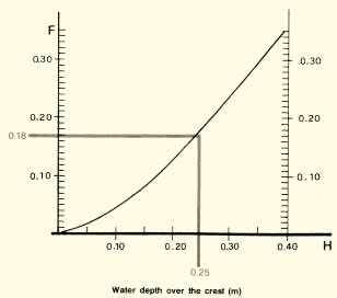
7. Knowing the value of Q, calculate the crest width W (in m) as
|
W = Q ÷ F |
where W (in m) is not larger than 1.5 m;
F is a factor depending on the maximum height H
(in m) of the water running over the crest of the spillway, usually
set at about 0.25 m (see Graph 13).
Note: if you determine that W should be greater than 1.50 m, it is often simpler to make two or even three spillway sections, each less than 1.50 m. If the mechanical spillway is wider than 4.5 m, you should not design it without the advice of an engineer.
|
Example The highest normal flow of the stream during the rainy season is calculated as 156 l/s.
8. Set the level of the crest as equal to the maximum water level in the pond. Note: the crest level plus the maximum water depth over the crest should not exceed the safe water level in the pond. There should still be at least 20 cm freeboard left around the dikes. |
Building a mechanical spillway |
||
|
9. You should wherever possible build the spillway on well-settled, natural soil. Unless it is specially reinforced and constructed, the normal pond dike itself is usually unsuitable, because soil movement will soon cause cracks in the structure and erosion will start damaging it further, together with the dike itself. A specially constructed spillway section within a dike is usually expensive and must be carefully built. 10. It is best to build the spillway away from the dike, and on the least sloping side of the valley. 11. You can build it with local stones, fired bricks or concrete blocks. You can also use concrete or reinforced concrete. |
Concrete block mechanical spillway
 |
|
Designing and building the spillway channel
12. The purpose of the spillway channel is to carry away the excess water discharged through the spillway and to channel it safely down to the level of the outside toe of the dike.
13. When designing and building the spillway channel, remember the following points:
(a) Lay the channel around the dike, at least 10 m away from its lateral end and 20 to 25 m away from its outside toe.
(b) The cross-section of the channel should be rectangular or trapezoidal and should be equal or greater than the wet cross-section of the spillway at maximum discharge.
(c) The freeboard in the channel should be at least 20 to 30 cm, based on the maximum expected flow.
(d) The overall drop in elevation of the channel should not normally exceed 1 m per 20 m length. Check the water velocity (see Section 8.2) to make sure it does not exceed the safe limits for the material you will use.
(e) If the drop in elevation is greater than 1 m per 20 m length, it is best to use:
- cobble or concrete-faced channel sections; or
- series of horizontal channels and drop structures (see Section 8.7); or
- a combination of these.
(f) If you are using a drop structure system, build the first horizontal section at or slightly below the level of the spillway crest, for a length of at least 5 m. You can also use a short sloped section immediately next to the crest.
(g) Build the last horizontal section at a level such that its water level is about the same as that of the receiving water.
(h) The drop structures can be made with rock, brick, block or, more commonly, concrete. You can also build a simple structure with wood, but this requires greater maintenance.
|
Section through spillway channel with drop
structures |

Example
For the previous case, spillway water flow is 0.152 m3/s. The difference in height between the maximum pond level (spillway crest) and the base level of the receiving point is 2.5 m.
The overall length of the channel is 30 m. Average fall is therefore: 2.5 m ÷ 30 m or 1:12, which is too steep. A channel with drop structures such as that shown would be preferred. Two or three drops will be sufficient, but a larger number of smaller drops can be used.
You will then need to check flow and velocity:
|
Section through crest
 |
11.4 The emergency spillway |
||
|
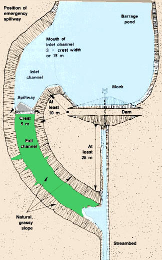
1. The purpose of an emergency spillway is to carry away exceptional
volumes of water in excess of the flow that can be discharged
under normal circumstances by the pond outlet, the pipe overflow
and/or the mechanical spillway. What is an emergency spillway?
|
 |
|
4. Generally, natural spillways should be preferred where possible, and spillways cut into rock are ideal.
 |

Note: in suitable circumstances you can combine a mechanical spillway with an emergency spillway |
Selecting a freeboard for the dike
5. When an emergency spillway is used, the minimum freeboard of the dike is the height of the top of the dike above the crest level of the emergency spillway (see also Section 6.1, ). This also defines the maximum height of water over the spillway before the dike is overtopped.
6. Select a shallow freeboard. For ponds with a maximum water depth of less than 3 m, the freeboard should be at least 0.60 m but not more than 1 m.
Determining the width of the emergency spillway
7. The width to be given to the spillway depends on a combination of the size of the catchment area that feeds the pond, the maximum flood to be discharged and the freeboard of the dike. To calculate the width of the emergency spillway proceed as follows:
(a) Determine the size of the catchment area (in ha) of your pond.
(b) Determine the flood discharge factor FD for a freeboard of 1 m maximum from the chart according to the size of the catchment area.
|
FD = flood discharge factor
|
|||||||||||||||||||||||||||||
(c) From meteorological records, obtain the mean annual rainfall (in mm) for the region where the catchment area is found.
(d) Determine the length of the catchment (in km).
(e) Determine the rainfall intensity factor RF from the chart, according to the mean annual rainfall and the length of the catchment.
|
RF = rainfall intensity factor
|
|||||||||||||||||||||||||||||||||||||||||||
(f) According to the predominant vegetation cover of the catchment, determine factor VF from the chart.
|
VF = vegetation cover factor
|
(g) According to the predominant nature of the soil in the catchment, determine factor SF from the chart. (Soil, 6, provides useful information on soils.)
|
SF = soil factor
|
(h) According to the overall slope of the catchment; determine factor PF from the chart.
|
PF = slope factor
|
(i) Calculate the topographical factor TF as TF
= VF + SF + PF
(j) Calculate the width of the emergency spillway (in m) required
as
|
W = FD x RF x TF |
where
FD is the flood discharge factor;
RF the rainfall intensity factor; and
TF the topographical factor.
Example
A catchment area of 150 ha is 2 km long. The average annual rainfall is 800 mm. The area is heavily grassed and has deep, moderately permeable soils. The overall slope is moderate (5 to 10 percent). The dike is to be built with a freeboard of 0.80 m.
(a) From the charts obtain successively: FD =
54; RF = 0.66; TF = 0.10 + 0.20 + 0.10 = 0.40
(b) Therefore W = 54 x 0.66 x 0.40 = 14.256 m.
Select an emergency spillway width of 15 m.
Designing the emergency spillway
8. When designing the spillway, remember the following:
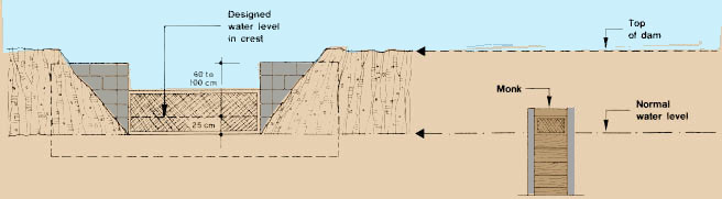
(a) The level of the spillway crest should be:
- 5 to 10 cm higher than the maximum water level if there is no mechanical spillway;
- about 25 cm higher than the level of the crest of the mechanical spillway, according to the maximum water depth allowed to flow through it (see Section 11.3).
(b) The length of the horizontal spillway crest should be at least 8 m.
(c) The side walls of the crest should have a slope of 3:1 or 4:1.
(d) The inlet channel should be reasonably short and have smooth, easy curves. Its bottom slope should be at least 2 percent, its side slopes should be at least 3:1, its entrance should be at least 1.5 times at wide as the crest width.
(e) The exit channel should be built in undisturbed soil whose natural slope is altered as little as possible. To avoid erosion, the bottom slope should be regular and not too steep. The direction of the slope should ensure that the discharged water will not flow against any part of the dike. The side slopes should be at least 3:1.
Note: whenever possible, select a natural channel for the spillway exit channel.
|
Sections through an emergency spillway
|
|


Locating the emergency spillway
9. The spillway should be built at one end of the dike, from which it should be separated by some undisturbed natural ground.
10. It should pass around the end of the dike and extend downstream on a gentle slope to some safe channel well away from the toe of the dike.
11. If necessary, you can use the same site for the emergency spillway as for the mechanical spillway and channel. However, you must be sure the channel can carry away the emergency water flow. Thus the spillway channel should be sized according to the emergency flows. As an approximate guide, the cross-sectional area of the channel should be that of the emergency spillway.
12. The characteristics and topography of the soils are very important in the selection of the spillway site. The soil should be natural, undisturbed and resistant to water erosion.
13. You should make detailed soil and topographical surveys before deciding on the site of your emergency spillway. Avoid loose sands and other highly erodible soils. Look for gentle and regular slopes.
Protecting the earthen emergency spillway
14. To prevent erosion by the turbulent water, you should protect the emergency spillway.
15. If the soil and climate do not allow the growth of vegetation on the bottom and side walls of the spillway, protect it as follows:
- strengthen the crest with wooden logs;
- cover the side walls with fixed brushwood or wooden boards; and
- use well-compacted rock, packed in with earth.
16. Whenever possible, protect your spillway with a dense grass cover, preferably using perennial grasses as recommended in Section 6.9.
(a) As soon as possible after construction, prepare the soil surfaces and apply fertilizers.
(b) Sow adapted grasses or transplant them.
(c) On the side slopes, protect the young grass by mulching*.
(d) Water well, if necessary, during dry periods.
11.5 Protection canals
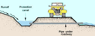
1. Protection ditches or canals are built to keep excess runnoff water from a particular area, and are usually built for one of three purposes:
- to protect a roadway or access track;
- to protect a water feeder canal;
- to protect a fish pond.
2. For the protection of a road or feeder canal, dig the canal uphill of and parallel to the road or feeder canal you wish to protect. It will collect and carry away the runoff by gravity. Depending on the local topography and the design of your fish farm, the runoff may have to be carried away along a route crossing the road or feeder canal. In this case, you can use a short pipeline (see Section 8.9) or an aqueduct (see Section 8.8) and have the runoff passing:
- either above the feeder canal or road;
- or below the feeder canal or road.
3. In the case of a road, you can also use a simple ford, or an angled surface channel.
4. When used for these purposes, protection canals are usually quite small, typically 0.5 to 1.5 m wide. You should check locally to see what is used for roadside ditches and use these as a guide.
5. To protect a fish pond, dig the protection canal uphill of and around the pond.
|
Protecting a water feeder canal
 |
Protecting a roadway
 |
|
|
Protecting a pond
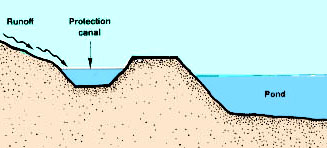 |
6. Such a canal can also be used to store rain-water during dry periods. The pond can then be supplied with water as necessary, even after its normal supply has dried out. In this case, you should build the protection canal so that its bottom level is higher than the maximum water level in the pond. An overflow should be built at its end to release any excess water.
 |
 |
7. A pond protection canal, if wide enough (3 to 4 m, for example), is also useful for limiting access to the pond.
Note: at some sites, it may be useful to build terraced storage ponds.
11.6 Settling basins
1. A settling basin is specifically designed to improve water quality by removing the mineral soil particles, such as fine sand and silt, which can be present in great quantities in certain waters with a high turbidity. This is achieved by reducing the water velocity sufficiently to allow the particles to settle. The ability of particles to settle is defined by their settling velocity Vs (in m/s), which decreases as the size of the particles decreases. The horizontal critical velocity Vc (in m/s), is also important. This is the speed of water flow needed to pick up and carry away a particle after it has settled. This velocity also decreases as particle size decreases. Typical values for these velocities are shown in the chart.
|
Settling velocity (Vs) and horizontal critical velocity (Vc) for soil particles
|
||||||||||||||||||||||||||||||||||||||||||||||||
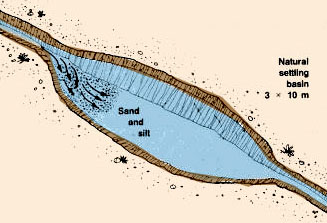
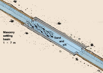
2. There are different types of settling basins:
- a simple small pond, built at the beginning of the water feeder canal;
- a rectangular basin built on the feeder canal with bricks, cement blocks or concrete.
 |
 |
Designing the settling basin |
||
|
Settling basin
 |
||
3. If the settling basin is a simple rectangular basin, you can determine its size as follows:
(a) Its minimum horizontal area B (in m2 ) as
|
B = (Q ÷ Vs) x E |
where
Q (in m3/s) is the maximum water flow to be discharged;
Vs (in m/s) is the settling velocity for the smallest particle size to be removed (see chart); and
E is the end allowance factor for extra space at each end needed to allow the water to run smoothly and evenly.
Typically E = 1.3 or 1.4.
Example
If Q = 30 l/s = 0.030 m3/s, to settle a particle which has a diameter greater than or equal to 0.1 mm, Vs = 0.007 m/s. Therefore the minimum horizontal area of the settling basin B = (0.030 m3/s ÷ 0.007 m/s) x 1.3 = 5.57 m2 = 5.6 m2. Take B = 5.6 m2.
Note: in these ideal conditions, 100 percent of particles of 0.1 mm or larger should settle. A smaller proportion of smaller particles will also settle. The smaller the particles, the less the percentage settling.
(b) The minimum cross-section area A (in m2 ) as
|
A = Q ÷ V |
where
Q (in m3/s) is the maximum water flow to be discharged;
V (in m/s) is the selected water velocity, which should be smaller than the critical velocity
Vc (see chart), according to the size of the smallest particle to be removed in the basin.
Example
Following the example above, select for example: V =
0.10 m/s, to avoid removing particles with a diameter greater than or
equal to 0.1 mm (from chart, for particles 0.1 mm in diameter, Vc
= 0.20 m/s). Obtain the minimum cross-section of the settling basin as
A = 0.030 m3/s ÷ 0.10 m/s = 0.3 m2.
(c) Its minimum width, w (in m) as
|
w = A ÷ h |
where
A (in m2) is the minimum cross-section area; and
h (in m) is the maximum water depth in the basin.
Example
If, for the example above, A = 0.3 m2 and h = 0.25 m, then the minimum width of the basin should be w = 0.3 m2 ÷ 0.25 m = 1.2 m.
(d) Its standard length, L (in m) as
|
L = B ÷ w |
where
B (in m2) is the minimum horizontal area; and
w (in m) is the minimum width.
Example
If for the example above, B = 5.6 m2
and w = 1.2 m, then the standard length
L = 5.6 m2 ÷ 1.2 m = 4.6 m.
(e) Its overall dimensions:
- inside width = w (in m);
- inside length = L (in m); and
- depth (in m) = water depth (h in m) + freeboard (0.20 m) + settling depth (0.10 to 0.20 m).
Example
For the above example, the settling basin characteristics will be:
- inside width, w = 1.2 m
- inside length, L = 4.6 m
- depth = 0.25 m + 0.20 m + 0.15 m = 0.60 m
Note: the settling basin can be wider, with a larger cross-section. This will then allow the standard length to be shorter. As long as the critical velocities are not exceeded, the basin can be shaped to fit local space and to minimize construction costs. As a general guide, ratios of length: width are typically between 2:1 and 5:1.
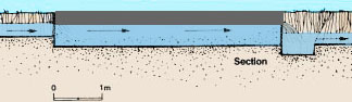
4. The bottom of the settling basin is built lower than the bottom of the water feeder canal, to concentrate the soil particles being removed from the incoming water.
Improving the design of the settling basin |
||
|
5. You can improve the above design in the following ways: (a) At the entrance, make the water pass over a wide edge near the basin's surface, similar to a weir, to minimize disturbances. (b) At the exit, similarly make the water spread over a wide edge near the basin's surface. (c) Avoid cross-wind exposure as this can often agitate the water and resuspend particles. (d) Within the basin, add some baffles to slow down the water further and make it follow a longer zig-zag path. With these baffles, you can reduce the basin's length by one third. (e) Make sure water flows evenly and quietly through the settling basin. Avoid creating areas of turbulence or rapid flow. (f) Provide a sloping bottom (slope = 2 percent) from the downstream end to the entrance of the basin. |
Improved settling basin
 |
|
6. You should regularly clean your settling basin by removing the accumulated soil from its bottom after closing the water supply. You can also remove this soil more regularly using a simple pipe or siphon. Usually, the soil is very fertile, and you should use it in your garden and fields to make your crops grow better.
11.7 Stilling basins
1. Stilling basins are commonly used to slow the water down as it emerges from the delivery pipe of a pump; such basins also help to settle out any sand sucked up by the pump. They can be further used as settling basins for finer soil particles, if designed properly.
2. The average velocity of the water discharged from the stilling basin should be reduced below the maximum velocity permissible in the feeder canal to avoid eroding it (see Section 8.2 and Table 35).
3. A stilling basin usually has a square base, with a height greater than its base dimension. It can be built with bricks, cement blocks or concrete.
Designing a stilling basin |
||
 |
||
4. When designing your stilling basin, you should proceed as follows:
(a) Determine the maximum water drop d (in m) between the water surface upstream of the basin and the water surface downstream, in the feeder canal.
(b) Estimate the minimum volume V (in m) to be given to the basin as
|
V= (Q x d) ÷ 125 |
where
d (in m) is the maximum water drop;
Q (in l/s) is the maximum water flow to be discharged.
Note: if you wish the stilling basin to also function as a settling basin (see Section 11.6), divide (Q x d) by 40 instead of 125.
(c) Determine the length L (in m) to be given to the basin as
|
L > 1.5 d |
where d (in m) is the maximum water drop (see above).
(d) Determine the water depth h (in m) in the basin as
|
h = h (feeder canal) + 0.10 |
where h (feeder canal) is the water depth (in m) in the feeder canal, downstream from the basin.
(e) Determine the inside width w (in m) of the basin, which should be greater than the width of the upstream canal, as
|
w = V ÷ (L x h) |
where
V (in m3) is the volume of the basin;
L (in m) is its length; and
h (in m) is the water depth.
(f) Determine the width of the water inlet (in m) at the basin's entrance as
|
w (water inlet) = w - 0.20 m |
where w (in m) is the inside width of the basin.
Example
If the maximum water drop d = 0.40 m and the maximum water flow to be discharged Q = 50 l/s, then:
-
V = (50 x 0.40) ÷ 125 = 0.16 m3;
-
L should be equal to or greater than 1.5 x 0.40 m = 0.60 m (make L = 0.70 m for example);
-
h = 0.30 m + 0.10 m = 0.40 m (with 0.30 m water in feeder canal);
-
w = 0.16 m3 ÷ (0.70 m x 0.40 m) = 0.16 m3 ÷ 0.28 m2 = 0.57 m; take w= 0.60 m;
-
w (water inlet) = 0.60 m - 0.20 m = 0.40 m.
Improving the design of the stilling basin
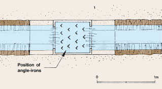
5. You can improve the above design by adding to the basin's bottom a series of angle-irons placed in alternating rows. These irons should be cemented vertically into the basin's bottom and should extend about 0.30 m above it.
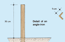 |
Improved stilling basin
 |