|
Open water
canals for a small fish farm |
1. Several different kinds of structure may be used to transport water on a fish farm. The most common one is the open canal, which we will consider in detail first (Sections 8.1 to 8.6). Then we will look at other common structures, including:
1. Different types of open water canals are used on fish farms to transport water, usually by gravity*, for four main purposes:
2. In this chapter you will learn about feeder, drainage and diversion
canals. You will learn more about protection canals later
(see Section 11.5).
|
Open water
canals for a small fish farm |
1. All canals should be well designed to have the required water carrying capacity. The canals are designed using formulas that relate the carrying capacity of the canal to its shape, its effective gradient or head loss, and the roughness of the canal sides. The most commonly used formula incorporating all these factors is the Manning equation:
|
v = (1 ÷ n) (R2/3) (S1/2) |
where
v = water velocity in the canal;
n = roughness coefficient of the canal sides;
R = hydraulic radius of the canal;
S = effective slope.
2. You will learn more about these terms below. First we will consider some basic design factors.
3. Water canals can have various shapes. In theory the most efficient shape is a semi-circle, but this is impractical for earthen canals. It is therefore generally used for precast concrete flumes* or plastic flumes only.
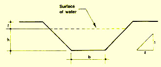
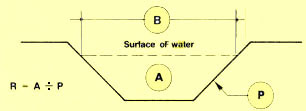
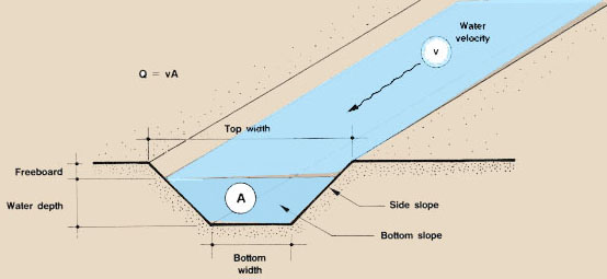
4. It is very common for unlined fish farm canals to have a trapezoidal cross-section, defined by:
5. When water canals are lined with bricks or concrete, they may also have a rectangular shape(see Section 8.3). |
 |
Selecting the side slope for a trapezoidal canal |
||
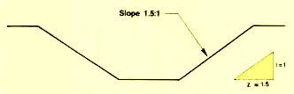
| 6. As you learned for pond dikes, the slope of the sides of a trapezoidal canal is usually expressed as a ratio, for example 1.5:1. This ratio is defined as the change in horizontal distance (here 1.5 m) per metre of vertical distance. The side slope can also be expressed in terms of the angle it makes with the vertical, in degrees and minutes. |
 |
7. The slope of the sides to select for an earthen trapezoidal canal depends on the type of soil in which the sides are cut (see Table 3.4). The more stable the soil material, the steeper the slope of the sides can be. If the canal is lined, the slope of the sides also varies according to the type of lining used.
8. The longitudinal bottom slope of earthen canals is determined according to topographical conditions:
9. The bottom level can be lowered whenever necessary by building drop structures in the canal (see Section 8.7).
10. In lined canals, such as those built of bricks or concrete, the bottom slope may be greater as there is less risk of damage by erosion.
11. In open canals, water velocity varies with depth and with the distance from the sides of the canal. Close to the bottom and next to the edges, the water flows less rapidly. When designing canals, you are normally concerned with the average velocity of the water across the entire canal cross-section.
12. The maximum average velocity that can be safely allowed in a canal to avoid erosion depends on the soil (see also Section 12.3, Soil, 6) or the lining material. Maximum permissible water velocities in canals and flumes* for various soils and linings are defined in Table 35.
|
TABLE 35
|
13. Knowing the bottom width b (in m) of the canal, the maximum water depth h (in m) and the side slope ratio (z:1), you can easily calculate the following characteristics of the canal:
|
 |
14. The geometry of the wet cross-section of canals is summarized in Table 36 for the three most common shapes: rectangular, trapezoidal and triangular.
Note: the greater the value of R, the greater the flow in the canal.
15. The coefficient of roughness (n) expresses the resistance to water flow created by the sides and the bottom of a canal. The greater the value of n, the greater the roughness of the canal walls, and the more difficult it is for the water to flow through the canal.
16. The values of the coefficient of roughness under various conditions are summarized in Table 37. Their reciprocal value (1 ÷ n) is also tabulated, to be used in later calculations.
|
TABLE 37
|
17. In simple cases, you can assume that the bottom of the canal will slope downstream. In fact, water will flow in canals as long as the water level is higher at the upstream end than the downstream end. If a canal has a horizontal floor, the gradient can be taken as the difference in head between upstream and downstream. The slope S of the canal bottom is expressed as metres of head per metre of canal length, for example S = 0.01 or 1 percent. The greater the value of S, the greater the flow.
| 18. Note that for steady, even flow and to minimize the risk of sedimentation, the canal should be built so that its bottom slope follows the overall gradient, i.e. the depth remains constant. Because they are easier to construct, however, canal bases are often made horizontal. |
When the slope is very little you can either measure
distance (d)
on the horizontal or distance (d') on the ground, with very little difference in the measurements 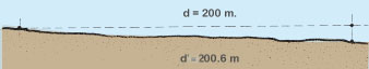 |
19. The Manning equation can be applied directly (see paragraph 25 in this section), or it can be used in a number of simplified forms.
20. If you plan to build a standard trapezoidal canal with a bottom width b = 1 m, sides slope z:1 = 1.5:1, and a flat longitudinal slope. S = 0.0001 to 0.0002 (0.01 - 0.02 percent), you can predict the approximate water capacity Q (in m3/s) of such a canal by assuming that the average water velocity will be v = 0.3 - 0.5 m/s, as follows:
Q = wet cross-section area x v
Example
If we select v = 0.3 m/s because of the relative roughness of the walls, the water carrying capacity of such a canal is estimated as follows:
* A = (b+zh) h with b = 1 m and z = 1.5; h from column 1
|
||||||||||||||||||||||||||
21. Another simple method is to use a table providing estimates of the water carrying capacity for a number of canal sizes, depths of water and longitudinal slopes. Table 38 provides such data for a trapezoidal canal cut in ordinary soil with side slope 1.5:1.
|
TABLE 38 |
22. If you plan to build a rectangular canal lined with brick, block or concrete (see Section 8.3), you can estimate its water carrying capacity (in l/s) as follows:
* Use first number for canals with rough walls and second number for those with smooth walls |
||||||||||||||||||||||||||||
|
Examples of rectangular lined canals
 |
 |
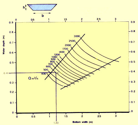
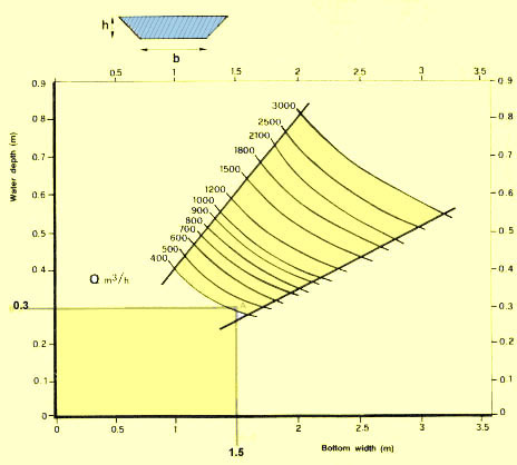
23. Graphs can also be easily used to design a water canal. See for example:
Graph 7, which gives the water carrying capacity of trapezoidal earthen canals with smooth walls, side slope 1:1 and a bottom slope S = 0.1 percent;
Graph 8, which gives the water carrying capacity of similar canals with rough walls.
24. You can use such a graph in two ways:
(a) You fix the characteristics of your water canal and you determine from the graph its carrying capacity.
Example
The canal has the following characteristics:
bottom width 1.20 m
water depth 0.40 m
side slope 1:1
bottom slope 0.1 percent
n = 0.020 (regular soil)
Using Graph 7, you determine point A. It corresponds to a carrying capacity Q = 620 m3 /h.
(b) You fix the water carrying capacity of the canal, and you determine from the graph the characteristics you require.
Example
If the canal has to have a carrying capacity of Q = 425 m3/h, being dug in a stony soil (n = 0.035) with side slope 1:1 and slope S = 0.1 percent, use Graph 8. Following line Q = 400 m3 /h, select a relatively wide bottom value (for example, 1.50 m) and determine point A at Q = 425 m3/h. From this point, determine water depth = 0.30 m on the left scale.
25. It is relatively easy to calculate directly the carrying capacity (in m3/s) of any open water canal with a uniform steady flow by using the Manning equation in the form
Q = A (1 ÷ n) R2/3 S1/2
where, as you learned previously,
A = wet cross-section area in m2
(Table 36);
R = hydraulic radius, in m (Table
36);
S = longitudinal slope of the canal bottom;
n = coefficient of roughness (Table 37).
26. To assist you with the calculations, you can also consult
Table 37, which gives some values of (1 ÷ n);
Table 39, which gives Ö1+z2, for common values of z;
Table 40, which gives the values of one-half powers (S1/2):
Table 41, which gives the values of two-third powers (R 2/3).
Example
A trapezoidal canal has the following characteristics:
bottom width b = 0.50 m
water depth h = 0.40 m
n = 0.030
S = 0.003
side slope z:1 = 1.5:1
Determine its carrying capacity as follows:
A = (b + zh) h = [0.50 m + (1.5 x 0.40 m)] x 0.40 m = 0.44 m2
(1 ÷ n) = 1 ÷ 0.030= 33.33
R = A÷ b + 2h (Ö1 + z2) = 0.44 m2 ÷ [0.50 m + (2 x 0.40 m) (1.80)] = 0.44 m2 ÷ 1.94 m = 0.227 m (Table 39)
R 2/3 = (0.227 m)2/3 = 0.372 m (Table 41)
S 1/2 = (0.003)1/2 = 0.055 (Table 40)
Q = (0.44 m2) (33.33) (0.372 m) (0.055) = 0.300 m3/s = 300 l/s
27. There are several ways by which you can calculate the average water velocity in an open canal. For example, you can use one of the following three simple methods:
(a) Knowing the water flow Q (m3/s) being carried by the canal with a wet cross-section area A (m2), determine the average water velocity v (in m/s) as v = Q ÷ A
Example
If for the above canal Q = 0.300 m3/s and A = 0.44 m2, then v = 0.300 m3/s ÷ 0.44 m2 = 0.68 m/s
(b) The average water velocity v (in m/s) can also be calculated directly using the standard Manning formula together with Tables 37, 40 and 41:
v = (1 ÷ n) R2/3 S1/2
|
Example If for the above canal, n = 0.030, R = 0.227
m and S = 0.003, |
TABLE 39
Remember: z from the side slope ratio expressed as z:1 |
|
TABLE 40
Remember: S = bottom slope expressed in units of vertical fall (m) per unit of horizontal distance (m) |
|
TABLE 41 |
How to use this table: if R = 0.227 m, determine R2/3:
in the first column, locate the R value down to its first decimal (0.2)
follow this line to the right until the column giving the second decimal (2)
mark this number down = 0.364, the answer for R = 0.220 m
follow the line until the next column to the right (3)
mark this number down = 0.375, the answer for R = 0.230 m
as R = 0.227 m is intermediate between these two values, you have to interpolate
calculate the difference between the two previous numbers, 0.375 - 0.364 = 0.011
divide this difference by 10 : 0.011 ÷ 10 = 0.0011
multiply the result by the third decimal of the R-value 0.227 m: 0.0011 x 7 = 0.0077
add this to the smallest number read from the table earlier: 0.364 + 0.0077= 0.3717 = 0.372
R 2/3 = (0.227 m) 2/3 = 0.372 m
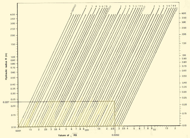
(c) You can use a graphic method to determine the average water velocity v (in m/s) as
|
v = C ÖRS |
C is obtained from Graph 9 in function of the roughness coefficient (1 ÷ n, Table 37) and the hydraulic radius R(Table 36);
ÖRS is obtained from Graph 10 in function of R, the hydraulic radius and S, the longitudinal slope of the canal bottom.
Example
For the same data as in the above example, find:
from Graph 9, for R = 0.227 m and (1 ÷ n) = 33.33, C = 26
from Graph 10, for R = 0.227 m and S = 0.003, ÖRS = 0.0262
v = C ÖRS = 26 x 0.0262 = 0.6812 = 0.68 m/s
28. Once you know the average water velocity v (in m/s), you can compare its value with the maximum permissible average velocity in your particular canal (see Table 35). The velocity v calculated by design should be smaller than the maximum permissible value, to avoid erosion of the canal.
Example
If the canal is dug in sandy loam, the maximum permissible average velocity is 0.8 m/s and your designed value v = 0.68 m/s is acceptable.
29. If the water carrying capacity Q (in m/s) of an earthen trapezoidal canal is known (once you have planned the fish farm, for example), it is easy to determine the characteristic dimensions for the best canal. Proceed as follows:
(a) According to soil quality, determine the maximum permissible
average velocity v max (m/s) from Table
35 and the side slope of the canal (z:1) from
Table 34.
(b) Define the coefficient of roughness n from
Table 37.
(c) Calculate the optimum wet cross-section area
(in m2) as: A = Q ÷ v max.
(d) Obtain the square root of A as ÖA.
(e) From Table 42, calculate
the characteristic dimensions of the optimum canal by multiplying
this square root by the numbers indicated on the line corresponding to the selected
side slope z:1.
Example
To design a trapezoidal canal to be dug in firm loam for a water carrying capacity of 1.5 m3/s, proceed as follows:
(a) From Table 35, maximum permissible
average velocity v max = 1 m/s.
(b) From Table 34, assume side slope 1.5:1.
(c) From Table 37, assume n = 0.025.
(d) Calculate A = 1.5 m3/s ÷ 1 m/s = 1.5 m2.
(e) Calculate ÖA = Ö1.5 m2 = 1.225 m.
(f) Using Table 42 for side slope 1.5:1, calculate the canal
characteristics:
water depth h = 0.689 ÖA = 0.689 x 1.225 m = 0.84 m
bottom width b = 0.417 ÖA = 0.417 x 1.225 m = 0.51 m
water top width B = 2.483 ÖA = 2.483 x 1.225 m = 3.04 m
wet perimeter P = 2.905 ÖA = 2.905 x 1.225 m = 3.559 m
hydraulic radius R = 0.344 ÖA = 0.344 x 1.225 m = 0.421 m
|
TABLE 42
|
||||||||||||||||||||||||||||||||||||||||||
30. For a given canal, the longitudinal slope S can be calculated as
|
S = (nv ÷ R2/3)2 |
where
n is the coefficient of roughness (Table 37);
v is the average water velocity, in m/s;
R is the hydraulic radius, in m (Table 41).
Example
For the above designed canal
S = [(0.025) (1 m/s) ÷ (0.421 2/3)]2
S = [0.025 ÷ 0.562]2
S = 0.002 = 0.2 percent
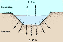
Losing water from an earthen canal |
||
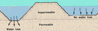
| 31. Water losses in earthen canals result from evaporation (1 to 2 percent) and seepage (5 to 40 percent). Seepage losses, which are by far the most important, vary according to the type of soil in which the canal is dug. |
 |
|
Water losses by type of soil
* See Soil, 6
|
|||||||||||||||||||||||||||||
Example
An earthen canal built in sandy loam has a wet perimeter P = 3.559 m. If its total length is 78 m, the wet soil area is 3.559 m x 78 m = 277.6 m2 . Total seepage losses will average 277.6 x 0.50 m3/day =138.8 m3 /day.
32. When designing feeder canals, it is advisable to include water losses averaging 10 to 20 percent according to the type of soil present.
33. If your water canal is very long, you can also adopt the rule of thumb saying that you will lose 10 percent of your water for each kilometre of canal.
Example
If at the main water intake you have 100 I/s of water available, after 1 km only 90 I/s will remain, and after 2 km only 81 I/s will remain.
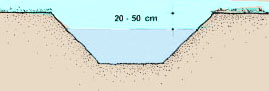
34. Until now you have learned a lot about the wet cross-section of canals. But, as already briefly mentioned at the beginning, the sides of the canal should be built a little higher than designed for a certain water carrying capacity to avoid overflow. This additional height of the walls, above normal water level, is called the freeboard.
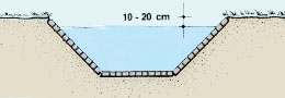
35. The freeboard varies according to the kind of canal:
in earthen canals, it varies from 20 to 50 cm
in lined canals, it varies from 10 to 20 cm.
36. You will learn more about freeboard in the next sections.
|
Freeboard in earthen canals
 |
Freeboard in lined canals
 |
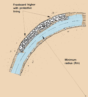
37. In some locations you may need to make the canal curve, for example to avoid a specific feature, or to take advantage of topographical conditions. Table 43 shows the minimum radius (Rm) of the curve allowable. As a general rule:
in firm soils, Rm = 20 x bed width in m;
in loose soils, Rm = 30 to 50 x bed width in m.
|
38. If necessary, make the freeboard higher on the outside of the curve, and line it to prevent erosion. For tighter bends, it is better to use stilling basins (see Section 11.7) or junction boxes (see Section 8.7). TABLE 43
|
 |
|||||||||||||||
39. In many cases you may have several choices of width, depth, gradient, side slope, etc. Some other practical factors may help you define your choice:
(a) If the water carries silt, too low a velocity will encourage the silt to settle out. You may wish to design an area specifically for this purpose.
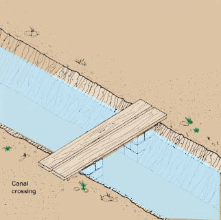
(b) If you need to cross the canal, it may be better to make it narrower at this point, possibly by lining the walls.
(c) If there are difficult or permeable soils at lower levels, you may wish to keep canals wide and shallow.
(d) If there are standard tools available for construction and maintenance, such as a bulldozer blade or a backhoe shovel, you may prefer to base canal sizes on these. Similarly, if you are using sheet polythene or concrete slabs* to line the canal, you may wish to size the canals to suit standard dimensions.
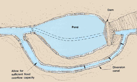
(e) Remember to allow sufficient capacity for floodwater likely to reach the canal.
|
Pool settling basin
 |
Canal crossing
 |
|
|
Locate canals above permeable soil
 |
Canal bottom width equal to width
of backhoe shovel 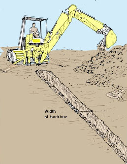 |
|
|
Barrage pond with diversion structure
 |
||
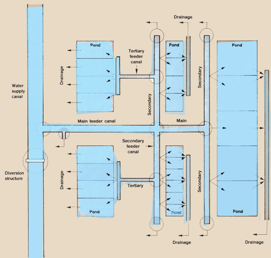
1. Water feeder canals, or supply canals, connect the main water intake to the various fish rearing facilities of the fish farm, and, in particular, to the diversion ponds. They can be ranked as primary (main), secondary or tertiary feeder canals according to their function on the farm.
2. When planning and designing your feeder canals, you should remember the following:
(a) The main feeder canal should bring the water to the farm site by gravity* at the highest possible level.
(b) On the farm sites, the canals should bring water to each facility by gravity.
(c) At each facility, the water level should be high enough to enable its drainage by gravity at any time.
(d) If pumping is needed, it is usually simpler to pump into a gravity supply canal, rather than pump out of each pond. Avoid having to do both.
(e) The level of the canal bottom should ideally be at least 10 cm higher than the normal water level in the pond it supplies. If the site slope is very gentle, however, the canal upper surface can be as little as 5 cm above the normal pond water level.
(f ) The main feeder canal should be as short as possible. If, for example, the longitudinal slope of the stream is less than 2 percent, it is best to raise its water level using a diversion structure to avoid digging too long a feeder canal (see Sections 8.2 to 8.9).
(g) The longitudinal bottom slope should be as small as possible. To decrease the canal level, it is best to use drop structures (see Section 8.7).
(h) The main canal should be designed so that all the ponds of the farm can be filled within five (total water area 5 ha) to 30 days (total water area 25 ha).
Example
A 4-ha fish farm contains 40 000 m3 of water in its fish ponds. These ponds should be filled within five days and therefore the water flow requirement Q = 40 000m3 ÷ 5 days = 8000 m3 /d = 0.093 m3/s = 93 l/s. So the main feeder canal should be designed for a carrying capacity of 93 l/s + 12 l/s (water losses) = 105 l/s.
(i ) Each pond should be filled within a minimum period of time according to its size, varying from a few hours for small ponds to a few days for large ponds. Design its feeder canal accordingly.
(j ) If possible, it is best to be able to fill two ponds simultaneously. Design the feeder canal accordingly.
(k) As far as possible, you should standardize the size of the feeder canals.
(l ) Feeder canals should be dug past the last pond they supply to a drainage point, to act as an overflow and automatically evacuate any excess water away from the farm.
(m) If there is a risk of excessive water runoff, you should build a protection canal (see Section 11.5).
3. For economic reasons, the size of the feeder canals should be kept to a minimum. When deciding on their dimensions, remember that:
(a) If you select the minimum wet cross-section A, you may have to increase the water velocity v to reach the necessary water carrying capacity Q because Q = vA. Be careful not to exceed the maximum permissible average velocity (see Table 35).
(b) If you need to increase the carrying capacity of a canal, it is better to widen than to deepen it.
(c) It is easier to maintain a shallow canal than a deep one.
(d) However, seepage losses are usually higher in surface soil. If your water supply is limited, a deeper canal might be better.
 |
|
Example
|
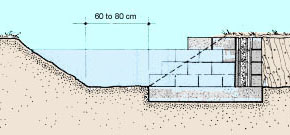
4. You may need to use lined feeder canals when:
the water supply is limited and soil seepage is high;
the lining material is locally available at reasonable cost;
feeder canals have to be built on the top of pond dikes;
feeder canals have to be built in soils very susceptible to erosion.
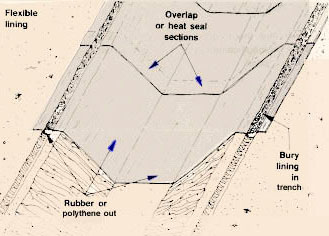
5. In certain situations, it may be more advantageous to build lined feeder canals using, for example, clay, fired bricks, concrete blocks or concrete. Butyl rubber or heavy-gauge polythene sheeting can also be used, although care has to be taken to avoid damage when laying the material. The sheets are usually laid singly in a series anchored at the top edge by bedding in trenches. Semi-circular, square or rectangular precast concrete sections can also be used, as is commonly done in irrigation schemes.
|
Brick or block feeder canal
 |
Concrete feeder canal
 |
|
|
Rubber or polythene feeder canal
 |
Precast concrete feeder canal
 |
6. Lined feeder canals have several advantages:
water losses are greatly reduced, normally averaging not more than 30 l/m2 of wet perimeter per day;
feeder canals can be relatively smaller, for example, when built in a rectangular or semi-circular shape;
the bottom slope can be increased, because the maximum permissible velocity of water is greater (see Table 35), which can contribute to size reduction;
they can be built above ground level or partially buried, which may considerably reduce the earthwork;
they are easier and cheaper to maintain;
they are not damaged by burrowing animals; and
they do not deteriorate when kept dry.
7. Major problems with canal linings may include:
deterioration of joints, especially in concrete linings;
cracking of the lining due to settlement of fill, erosion of material, swelling of clay soil or very poor quality of concrete;
cracks in joints and penetration of cracks by weeds are a frequent cause of progressive deterioration of canal linings;
higher initial investment;
flexible liners may tear, harden in sunlight or may pull out of their bedding-in trenches.
8. Common dimensions of lined feeder canals vary according to their shape:
for rectangular cross-sections, see Section 8.2;
for trapezoidal cross-sections, the bottom width of the canal usually varies from 0.5 h to 1 h, h being the water depth.
1. You have already learned in the previous volume in this series, Topography, (Sections 8.2 and 8.3), how you should first survey the possible route the canal can take between the main water intake and the fish ponds by contouring and profiling (longitudinal profile and cross-sections).
2. You have also learned how to stake out the centre line* of the canal, once its route has been defined, taking into account the possible presence of rocks underground by spot checks with a soil auger (see Soil, 6). If necessary, identify the location of the drop structures you will have to build to avoid bottom slopes that are too steep (see Section 8.7).
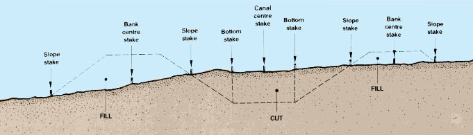
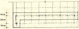
3. Now you should carefully stake out the canal cross-section.
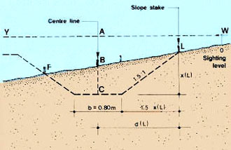
4. If the canal is all in cut* and requires no
artificial banks:
|
Canal centre stake
 |
5. If the canal has two artificial banks, its cross-section being built partly in cut and partly in fill*:
on each side of the centre stakes set bottom stakes and slope stakes as above, showing the limits of the cross- section in cut;
on each side of the canal centre stakes, set bank centre stakes at distances which remain constant as long as the canal section does not change;
on the external side of the bank centre stakes, set the bank slope stakes, showing the limits of the cross-section in fill.
|
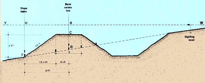
6. If the canal is on the side of a hill and has one artificial bank built on the downhill side of the canal, the canal bottom should always be built in cut for its full length:
on each side of the centre stakes, set bottom stakes and slope stakes as above, showing the limit of the cross- section in cut;
on the downhill side of the canal centre stakes, set the bank centre stakes at a distance which remains constant as long as the canal section does not change;
on the downhill side of these bank centre stakes, set the bank slope stakes, showing the downhill limit of the cross-section in fill.
|
Setting slope stakes on sloping ground.

|
7. As far as possible, you should try to balance the earthwork in cut and fill. This is best done from cross- section profiles (see Section 9.6, Topography).
8. The distances from a centre line at which to set the slope stakes vary with the slope of the ground. To establish their correct position you will need to proceed step by step, by trial and error, as described in the example.
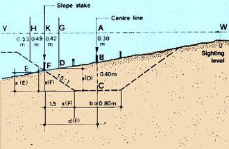
9. The method to use is based on the fact that the distance d (in m) from a centre stake to the slope stake should be:
|
d = (b ÷ 2) + (xz) |
where
b is the canal bottom width, in m;
x is the depth or height of cut or fill, at the slope stake, in m and
z is the side slope, or ratio of horizontal distance to drop or rise.
Example
A canal is to be cut in a hillside with the following characteristics:
b = 0.80 m and z = 1.5. The slope
stake is to be set on the left of the canal centre stake.
 |
10. Using this example, proceed in the following way:
(a) From a fixed levelling station at 0, establish the horizontal line of sight WY using a sighting level (see Sections 5.4 to 5.9, Topography).
(b) Measure height AB = 0.30 m at the canal centre stake.
(c) From the design, you know the elevation of point C, on the centre line of the canal bottom as E(C) = 102.33 m.
(d) From the longitudinal profile of the canal centre line, you know the elevation of point B as E(B) = 102.73 m.
(e) Calculate height BC = E(B) - E(C) = 102.73 m - 102.33 m = 0.40 m.
(f) Calculate height AC = AB + BC = 0.30 m + 0.40 m = 0.70 m.
(g) As a first trial, hold the levelling staff at D and measure DG = 0.42 m.
(h) Calculate x(D) = AC - DG = 0.70 m - 0.42 m = 0.28 m.
(i ) Using the formula, obtain the computed d(D) = (0.80 m ÷ 2) + (0.28 m x 1.5) = 0.82 m.
|
(j ) Measure horizontal distance AG = 0.37 m, this distance is smaller than the computed distance d(D). Therefore, the slope stake position should be further away from the centre stake. (k) As a second trial, hold the levelling staff at E
and measure (l ) Calculate x(E) = AC - EH = 0.70 m - 0.53 m = 0.17 m. (m) Using the formula, obtain the computed d(E) (n) Measure horizontal distance AH = 0.73 m, this distance is greater than the computed distance d(E). Therefore, the slope stake position should be closer to the centre stake. |
 |
|
|
(o) Move the levelling staff slightly closer to the centre stake and eventually hold it at F where you measure FK = 0.49 m. (p) Calculate x(F) = AC - FK = 0.70 m - 0.49 m = 0.21 m. (q) Computed d(F)= (0.80 ÷ 2) + (0.21 m x 1.5) = 0.715 m. (r) Measure horizontal distance AK = 0.72 m. This distance is practically equal to the computed distance d(F) which shows that F is the correct location for slope stake F. (s) Repeat the same procedure, from the same levelling station O, to determine the correct location for slope stake L. |
 |
(t) Repeat the same procedure to locate bank slope stakes whenever necessary, with:
 |
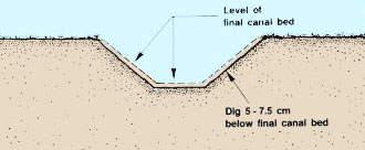
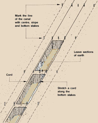
11. An earthen canal is constructed in several steps.
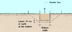
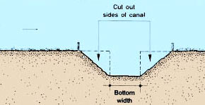
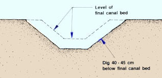
(a) Mark the length of the canal with centre, slope and bottom stakes as discussed above. Stretch a length of strong cord along the bottom stakes to mark the first cut. Dig out a vertical trench as wide as the canal bottom:
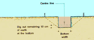
dig to a depth of 10 cm higher than the final depth using the centre stakes as reference points;
leave sections of earth to hold the stakes in place until you have finished digging the centre trench;
carry away the earth that you dig out to build banks or throw it downhill to avoid later erosion by runoff into the finished canal.
Note: if you use the earth to build banks, make sure that it is well compacted (see Section 6.2, Construction).
 |
 |
|
|
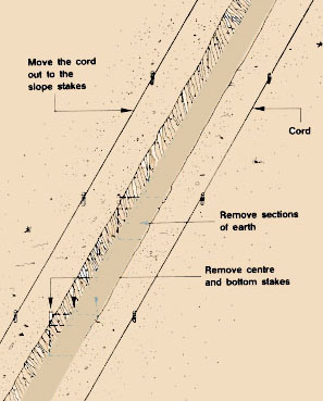
(b) Move the lengths of cord out to the slope stakes to mark the next
cut. Remove the centre and bottom stakes and the sections of earth that
you left to hold these stakes in place. |
 |
|
 |
||
|
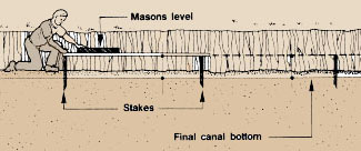
Adjust slope of canal bottom if necessary
 |
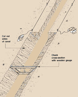
(d) Cut out the sides of the canal from the side stakes obliquely to the edges of the canal bottom:
use a wooden gauge to check the cross-section of the canal as you dig;
get rid of the earth as you were told before.
 |
 |
(e) Complete the construction of the banks if necessary, levelling the top and forming the external side slopes. Plant grass to avoid erosion (see Section 6.9).
(f ) Build the water control structures before letting any water flow through the canal (see Section 8.7).
(g) After you have finished check that the canal functions as designed by letting in some water before starting the construction of the diversion ponds.
Building a clay-lined canal |
||
|
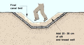
12. Where good clay is available (see Soil, 6) and where the canal is not dried out seasonally, a clay lining can reduce seepage by 75 to 80 percent:
|
 |
|
|
 |
|
|
 |
|
Building a concrete-lined canal |
||
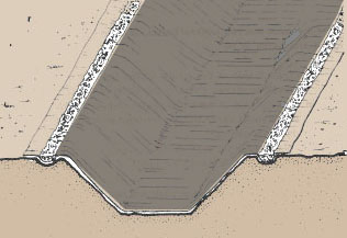
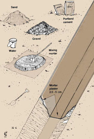
| 13. Where sand, gravel and Portland cement are available,
poured concrete linings are usually preferred to precast materials
or fired bricks, because of their long life. Their construction also requires
less effort.
14. Small cement-concrete linings can be easily formed by plastering
the faces of the canal with mortar, after the ditch has been properly
dug to its designed dimensions (increased from 2.5 to 5 cm by the thickness
of the mortar). Refer to Section 3.3,
where you learned about cement mortars.
Another possibility is to use soil cement if soils are suitable.
15. Larger canals are better lined by using wooden forms. Cement concrete (see Section 3.4) is then placed between the forms and the earthen walls. Remember the following points: (a) The required thickness of the lining varies from 5 to 7.5 cm, depending on the size of the canal. (b) Side slopes may be 1:1 in rocky soils, but for most other soils a slope of 1.5:1 is preferred. (c) Dig the earthen canal as explained above, increasing its designed dimensions according to the thickness of the concrete.
|
 |
|
|
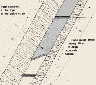
(d) First line the canal bottom by building a series of concrete guide strips about 10 cm wide at 10 m intervals, their top surfaces being at the exact elevations indicated by the design. (e) Let these strips harden, and complete the bottom lining by pouring concrete between them, using them as reference points to give the canal bottom its designed height and slope. |
 |
|
|
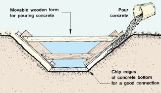
(f) Metal or wooden forms can be used when pouring the concrete.
Note: joints should be placed between poured sections at 2 to 4 rn intervals to prevent cracking resulting from expansion or contraction of the concrete caused by temperature and humidity changes. |
 |
|
|
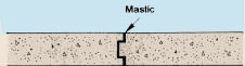
Expansion joints |
||
|
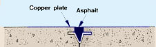
Notch joint and mastic fill
 |
Folded copper joint filled with asphalt
 |
|
|
Notched joint with steel plate and mastic fill
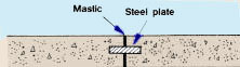 |
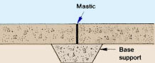
Butt joint with base support and mastic fill
 |
|
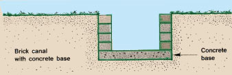
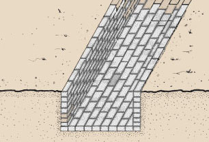
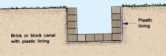
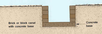
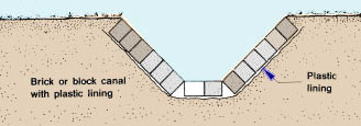
16. Small brick or block-lined canals can be built either in a rectangular or in a trapezoidal shape. The floor may be built either of brick or concrete. For additional seepage control, a plastic lining may be set behind the walls and under the floor.
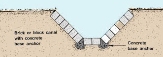
17. For larger channels a trapezoidal shape is normally used; its side walls are supported by the cut embankment or by lateral fill, which must be firm and well compacted to avoid settlement and cracking of the bricks.
18. Standard or vertical-wall canals for fish farm use are normally of single brick or block thickness, although where lateral strengthening is required, small piers or bracing points may be incorporated. If hollow or notched concrete blocks are used, simple reinforcement can easily be added.
Note: brick is laid either in conventional horizontal runs, face or side down, or diagonally in "herringbone" fashion, bedded on 10 to 15 mm of 1:5 cement mortar, with 1:3 jointing mortar.
|
Rectangular
 |
 |
|
|
Trapezoidal
 |
 |
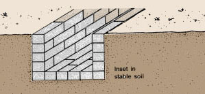
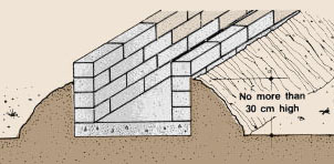
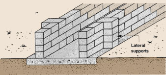
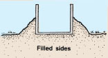
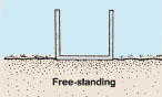
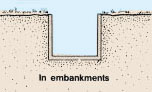
19. Rectangular channels can be constructed either inset in an embankment or with filled sides (with fill on each side not exceeding 30 cm), or partially or completely freestanding, in which case lateral strengthening may be needed to protect against impact damage.
20. For brick channels, the outside fill slope should be no steeper than 45° (1:1 ratio); thus a rectangular channel filled to 60 cm of its height will have fill at least 60 cm wide on either side. Trapezoidal canals are filled to their upper edge or higher (forming a small embankment). As the slope is based on the upper canal width, the quantity of fill material is consequently much greater and the base much wider than that of vertical-sided channels.
21. The main problems of using brick are the relative cost and slow speed of construction, and rigidity, which may lead to cracking if the base material is not compacted properly or if lateral soils (e.g. clays) are prone to swelling or settlement. Plastic lining may be used to limit damage from seepage, which may otherwise accelerate cracking and deterioration. Take particular care to ensure that bricks are sound and that mortar is of good quality and will not wash out.
|
Various examples of rectangular canals
|
||
|
Insert in stable soil
 |
Filled sides
 |
|
|
Free-standing with lateral supports
 |
||
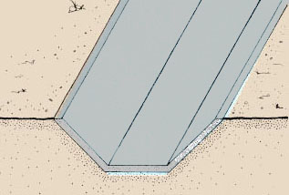
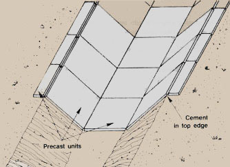
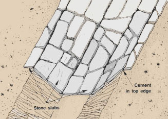
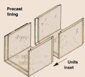
22. Precast cement units or cut stone slabs may also be used for lining, set either on a slab, brick or concrete floor. These are usually in trapezoidal canals, with lateral support at the top edge. As with bricks, poor base materials may result in cracking of the mortar and of the slabs themselves.
23. Normally single slab units are used on side walls. They limit effective wall height and hence canal depth. A mortar fill of 5 to 10 mm is normal, and the bottom edge of the wall slabs should be well supported on the base to avoid collapse. As with brick walls, an external plastic lining can help reduce deterioration through cracking.
|
Precast cement slab lining
 |
Cut stone slab lining
 |
24. A range of manufactured concrete linings is produced for agriculture, drainage and waste water use. If available locally, they may be an effective choice. They are normally integrally cast - walls and base form a single unit - and can be used backfilled, in embankments or freestanding. They are produced either lightly reinforced or unreinforced. The unreinforced linings are weaker and may be somewhat permeable if poor quality aggregates are used. In this case, internal plastering or external lining with polythene is recommended. Units are now also available in glass reinforced plastic (fibreglass) - which is light, strong and smooth-walled, but relatively expensive - and in glass reinforced cement, which is cheaper but heavier. Asbestos cement linings are also available in some locations.
 |
 |
 |
 |
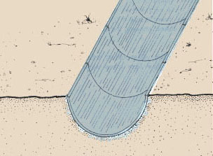
25. As mentioned earlier, several flexible materials, such as rubber or polythene, may be used. They have the advantage of good adaptation to ground shape and initial settlement or swelling, and can normally be laid relatively quickly in long continuous lengths. Adjacent lengths can be either heat sealed, cemented or simply overlapped. The sides are carried over the upper edges of the canal and dug into trenches, typically 30 to 40 cm deep and backfilled with earth or aggregate.
| 26. The main disadvantage is the ease with which they are damaged, through puncturing by sharp objects or coarse underlay material; once damaged the base material is easily washed out. Exposure to strong sunlight and high surface temperatures can make many of these materials more brittle and hence more prone to damage. Reinforced linings, although more expensive, are more durable. For this reason, these linings are often covered with soil, clay, brick or slab. Polythene sheet may also be useful as an anti-seepage lining for more rigid materials such as brick or slab. |
 |
1. Drainage canals are built to carry the water draining from the fish ponds away from the farm site, usually into a lower natural channel.
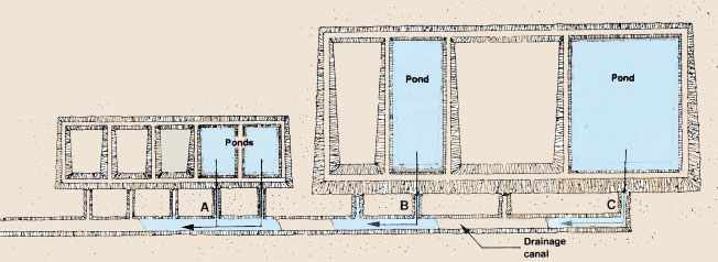
2. The design of a particular drainage canal should be based on the pond or series of ponds it will have to drain:
for small ponds, (nursery ponds, for example), the drainage canal may be designed to drain more than one pond simultaneously, within a period of perhaps a couple of hours;
for medium-size ponds, the drainage canal is usually designed to drain the ponds one by one within a reasonable period of time, from half a day to a full day;
the design of the drainage canal also depends on the type of pond outlet and its water carrying capacity (see Chapter 10);
for large fish farms, the total drainage time of all the ponds should not exceed 1 day per hectare (or 5 days for a 5-ha water surface and 25 days for 25 ha); the pond outlet structures should be designed accordingly.
3. Drainage canals are usually unlined and trapezoidal in cross-section. They are designed and built as described in Sections 8.3 and 8.5.
4. Remember that to ensure good and complete drainage, the lowest level of a drainage canal should be at least 20 cm deeper than the lowest point in the pond.
|
About drainage canals
 |
||
| A Drain small ponds two or more at a time B Drain medium-size ponds one by one C Drain large ponds one by one |
||
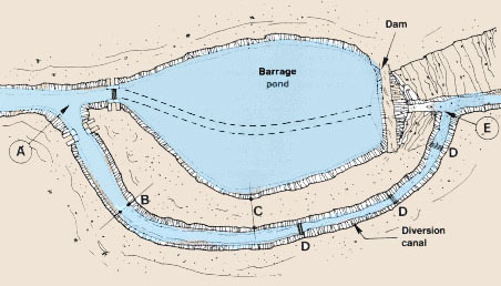
1. A diversion canal should be built to divert excess stream water around a barrage pond if the pond is built where there is a likelihood of floods. Such a canal should therefore be deep and wide enough to evacuate the largest flood waters. The diversion canal starts from a diversion structure (see Sections 7.3 to 7.5).
2. Design and construction methods of diversion canals are similar to those given for earthen feeder canals (see Section 8.3). The following points are of particular importance:
the canal's initial bottom level should be equal or slightly lower than the stream bottom level;
the canal dimensions should be at least equal to those of the stream channel when in full flood;
the canal should be at least 5 m away from the pond banks;
when staking out the canal axis, set all the tops of the stakes at the same level;
it is best to design the canal bottom with no slope and to build a series of drop structures at regular intervals (see Section 8.7). The total height of these drops should be equal to the difference in elevation between the initial canal bottom at point A and the original stream bottom at the junction point E;
when digging the canal, start from its downstream end.
Note: consider constructing a diversion canal only if its dimensions are reasonable; if not, it might be best to select another site for a barrage pond or to study the possibility of having diversion ponds.
|
About diversion canals
 |
||
| A Bottom level of inlet equal to or lower than bottom
level of stream B Canal width equal to stream width at times of flood C Canal at least 5 m away from pond banks D Drop structures E Start digging canal at the downstream end |
||
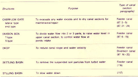
1. Several kinds of water control structures are used in feeder canals for various purposes, see Table 44.
2. These structures can be built with a range of materials such as wood, fired bricks, concrete blocks or concrete, according to local availability and size of the fish farm. Refer to Chapter 3 to select the right kind of material and to use it properly.
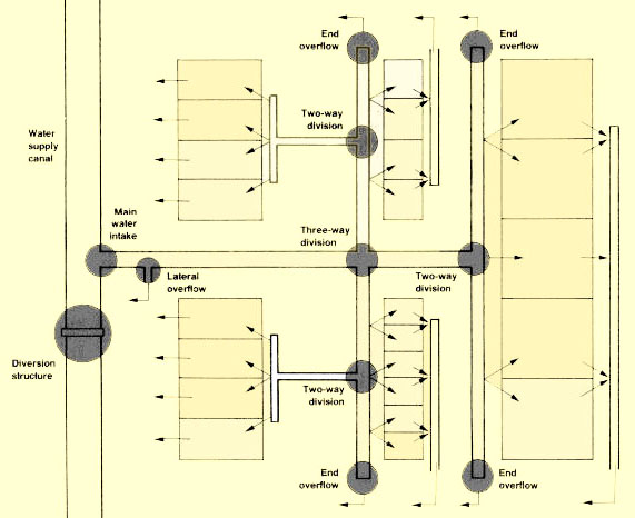
|
Water control structures
for a small fish farm |
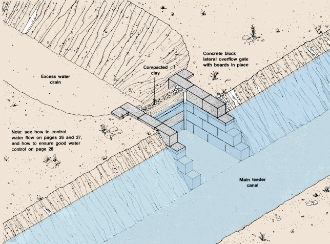
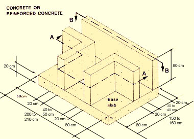
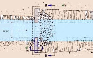
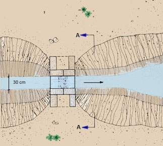
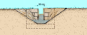
3. To guard against damage from sudden rises of the water level in feeder canals, a lateral overflow gate should preferably be built immediately downstream from the main water intake. Other similar gates should also be built further down, on the various feeder canals.
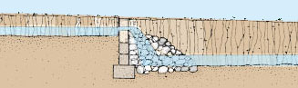
4. Lateral overflow gates are built in one of the side walls of the feeder canal. They are usually box-like structures with a set of two grooves in their lateral walls. Wooden planks are placed into these grooves up to a level slightly higher than the normal water level in the canal. Clayey soil is well packed between the two rows of planks to control any water seepage. When the canal has to be completely drained for maintenance or repair, the earth and the planks are removed.
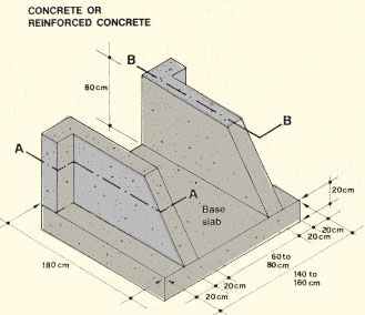
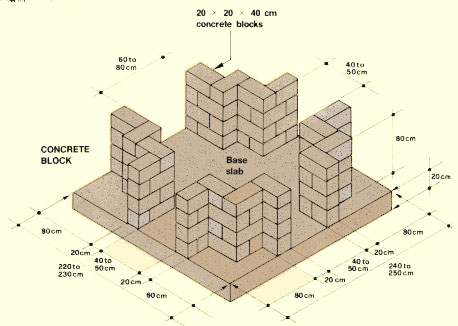
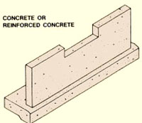
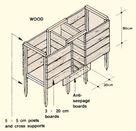
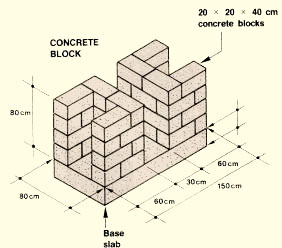
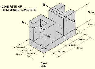
5. Lateral overflow gates can be built from wood, bricks, concrete block or reinforced concrete.
|
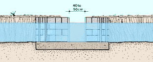
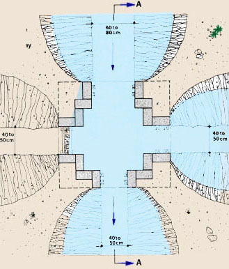
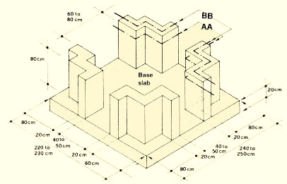
Plan of concrete block lateral overflow gate
 |
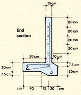
Section AA
 |
|
|
|
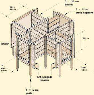
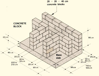
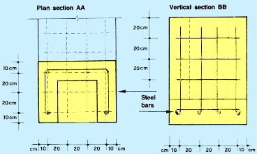
Building a lateral overflow gate
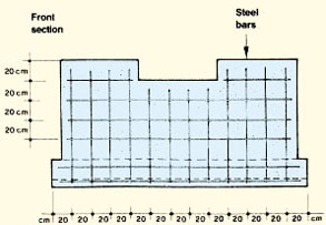
 Placement of steel bars for reinforced concrete |
 |
|
Plan section AA
 |
 |
|
| Note: the dimensions shown are suitable for a medium-size pond system; dimensions may vary, however, depending on the size of your pond system |
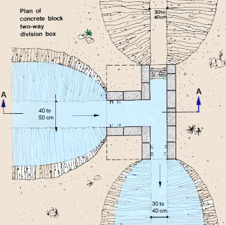
6. A three-way division box (X-box) is used in a feeder canal to divert part of its water flow or its total flow into either:
one or two pond intakes; or
one or two additional feeder canals.
7. Such diversions are usually done at right angles. They offer the same possibilities as T-boxes (see paragraphs 11 to 15 in this section), but with an additional gate.
8. Three-way division boxes are built across the feeder canal and two diversions. They are x-like structures with three gates and sets of grooves, either single or double. Wooden planks make it possible to close or regulate the water flow through each gate independently.
9. The width of each side gate should be proportionate to the water flow they have to accommodate. The width of the front gate also varies according to the flow passing through it.
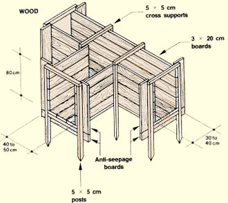
10. Three-way division boxes can be built of wood, bricks, concrete block or reinforced concrete (see Chapter 3).
|
Plan of concrete block three-way division box
 |
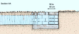
Section AA Building a three-way division box |
|
 |
||
|
Concrete or reinforced concrete
 |
||
|
Placement of steel bars for reinforced concrete
Plan section AA 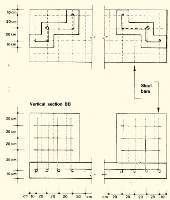 |
||
Note: the dimensions shown are suitable for a medium-size pond system; dimensions may vary, however, depending on the size of your pond system
11. A two-way division box (T-box) is used in a feeder canal to divert part of its water flow or even its total flow into either:
one water intake of a pond; or
one additional feeder canal.
12. Usually such a diversion is constructed at a right angle. The division box also makes it possible to regulate the quantity of water flowing into a particular pond or canal at any time. Maximum flow into the pond is obtained by raising the water level within the canal and fully opening the pond intake connection. No water is admitted into the pond whenever the pond intake connection is blocked.
13. Two-way division boxes are built across both the feeder canal and the pond water intake. They are T-like structures with two gates and sets of either single or double grooves. Wooden planks placed in these grooves serve to close or regulate the flow through each separate gate independently.
14. The width of the side gate should be proportionate to the water flow it has to accommodate. The width of the front gate usually does not differ from that of the box entrance.
15. Two-way division boxes can be built of wood, bricks, concrete block or reinforced concrete (see Chapter 3).
 |
 |
|
|
Building a two-way division box
 |
||
 |
||
| Note: the dimensions shown suitable for a medium-size pond system; dimensions may vary, however, depending on the size of your pond system |
Placement of steel bars for reinforced concrete
Plan section AA 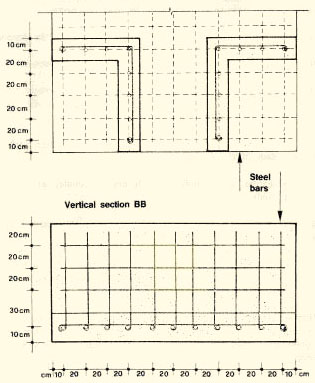 |
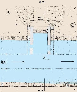
16. Drop structures should be used in feeder canals and diversion canals whenever the bottom slope must be reduced to slow down the water below its permissible velocity (see Section 82). When the water flow is relatively large, it is always better to have a near-horizontal canal bottom and to build drop structures whenever it becomes necessary to lower its relative elevation.
17. Drops can be built in various ways from wood or concrete. For their design and construction, remember the following points:
(a) Both the sides and the base of the structure should be deeply and firmly set into the soil.
(b) The top level should be slightly higher than the upstream level of the canal bottom.
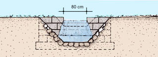
(c) Widen the canal cross-section immediately downstream from the drop, deepen the canal bottom downstream and protect this part either with stones or concrete.
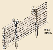
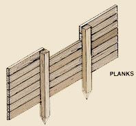
18. For a wooden drop use water-resistant wood (see Section 3.1). You can use:
lengths of tree limbs, 10 to 15 cm in diameter; or
planks.
19. Make sure the structure is well bedded in and that the wood is securely fastened.
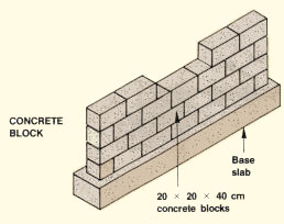
20. When building a concrete or brick drop, remember that because it is heavy it must be well built. Make sure the foundation is well set up and that there is no risk of erosion along or below its edge.
Note: you can also use smaller drop structures, usually made from wood or brick, for falls of less than 20 cm. They are simpler and can be more lightly constructed, but you will need more of them for the same overall drop.
|
Plan of drop structure
 |
Section AA
 |
|
|
Section BB
 |
|
Building a drop structure |
||||
 |
 |
 |
||
|
Placement of steel bars for reinforced concrete |
||||
 |
 |
 |
||
21. End overflow gates should be built at the end of every feeder canal to drain any excess water away from the ponds, for example, in a drainage canal or a natural depression or channel.
22. A simple overflow gate can be made from a pipe placed at a level higher than the level of the pond inlets.
23. It can also be built within the feeder canal section as a rectangular box-like structure with two sets of grooves. It is used in the same way as lateral overflow gates (see paragraphs 3 to 5).
24. End overflow gates can be built of wood, bricks, concrete block or reinforced concrete using the same methods.
|
Plan of concrete block end overflow gate
 |
Section AA
 |
|
|
Building an end overflow gate
 |
 |
|
 |
Placement of steel bars for reinforced concrete
 |
Note: the dimensions shown are suitable for structures for a medium-size pond system
1. Aqueducts are used on fish farms to transport water above ground level, for example a main feeder canal crossing over a small drainage canal.
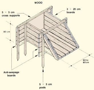
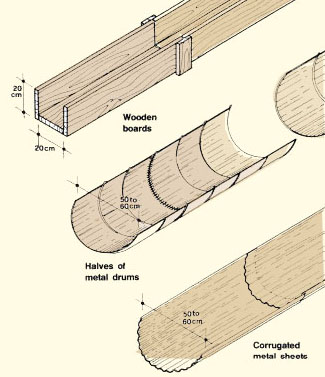
2. A simple aqueduct can be built of wooden boards, assembled with wooden cross-bracing and supported by a wooden framework at regular intervals. Its cross-section is usually rectangular. Maximum permissible average velocity should be limited to 1.5 m/s (Table 35). The water carrying capacity of such an aqueduct can be estimated as explained earlier (see Section 8.2), using a coefficient of roughness n = 0.014. Therefore (1 ÷ n) = 71.43.
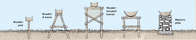
| 3. Another possibility is to use 200-litre metal drums
cut into two halves, welded or bolted together and fixed over a platform
built of wood or rock.
4. Corrugated metal sheets can be easily assembled lengthwise with flexible tarred joints and welding points to form a semi-circular aqueduct, similar to those built of precast concrete flumes or plastic flumes for irrigation purposes. Supports can be similar to those described for half metal drums. |
 |
|
Various ways to support an aqueduct
 |
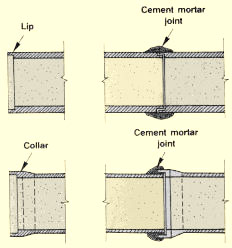
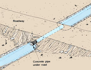
1. When water carried in open canals must be conveyed under roads or other obstructions, a short pipeline can be used. It should be strong enough to support the weight of vehicles passing over it. Precast concrete pipes buried at least 60 cm under the road surface are often used (see Section 3.8). Particular attention should be paid to:
the quality of the joints between the pipe sections; and
the quality of the end connections between the pipeline and the open canal section on either side of the road.
|
Example Characteristics of short pipelines for road crossings
|
 |
|||||||||||||
| 2. More details on laying pipes and preparing pipe foundations are given in Chapter 10. |
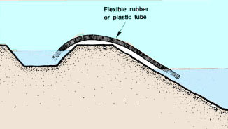
4. A siphon is an inexpensive device that can be carried to different points of the fish farm according to need. It can easily be made from a piece of flexible rubber or plastic hose. If the total length of the siphon is relatively short, for example for transferring water from a shallow feeder canal to a small pond, you can also make a more durable rigid siphon:
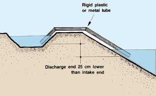
by bending a piece of plastic tube;
by bending pieces of galvanized sheet metal to shape them into tubes, carefully soldering all seams so they are airtight and assembling these segments to form a truncated V-shape by further soldering;
by cutting and connecting (with cement or solvent cement, by welding, etc.) a metal or PVC pipe.
5. To start a siphon, remember that you have to fill it first with water. Place the discharge end of the siphon at least 25 cm lower than the intake end. Keep the intake end well under water and let the water flow out of the filled siphon. To be successful you may need some practice, especially if the diameter of your siphon is large (see also Section 10.2).
|
Draining by siphon
 |
 |
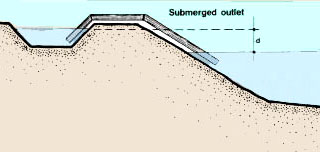
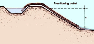
6. The water discharge capacity of a siphon depends on:
the inside diameter of the tube;
the head or difference in elevation between the water surface on the upper level and either the water surface on the lower level (if the siphon outlet is submerged), or the centre of the siphon outlet (if it is free flowing).
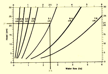
7. You can estimate the water discharge capacity of your siphon (in I/s) from Graphs 11 and 12 on the basis of these two measurements. You can also use Table 45 for small siphons and low pressure heads.
Example
The inside diameter of your siphon is 5 cm; the head is 21 cm. From Graph 11 find the water discharge capacity equal to about 2.5 l/s.
The inside diameter of your siphon is 18; the head is 27.5 cm. From Graph 12 estimate the water discharge capacity equal to 35 l/s.
|
Water discharge capacity
 |
 |
|
|
Difference (d) in elevation between upper and lower
water surface
|
Difference (d) in elevation between upper water
surface and centre of lower siphon outlet
|
|
|
GRAPH 12
Siphons with an inside diameter larger than 9 cm 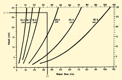 |
|
TABLE 45
|
|||||||||||||||||||||||||||||||||||||||||||||||||||||||||||||||||||||||
![]()